Contents
Introduction
This Module details Durability and monitoring requirements for CO2 storage in the built environment. Within this Module, a built material is defined as concrete within which CO2 is stored in the form of carbonate minerals or carbonated materials incorporated into concrete, which can be used in various construction applications. Furthermore, durability refers to the stability of CO2 stored in concrete, and the length of time for which carbon is removed from the Earth’s atmosphere (>1,000 years) and cannot contribute to further climate change. Note that in the context of the built environment, the term durability is typically used to refer to the structural durability of concrete. Within this Module, that is referred to as concrete durability.
Built materials used for the construction of buildings or infrastructure projects may be exposed to variable environmental conditions during their functional use life and during end-of-life treatment. Such variations can influence the stability of stored carbonate minerals within the built material. For the purpose of this Module, built materials are treated as an open system storage mechanism. In comparison, closed systems are isolated from external environmental changes, potentially offering a more controlled and secure environment for the long-term storage of mineralized carbon. The stability of carbon within the built material, and thus its durability, depends on interactions with the surrounding environment and intended use case. Potential risk factors which may affect the expected durability of carbon in built materials include, but are not limited to:
- Interactions with acidic fluids (e.g. acid rain, low-pH groundwater)
- Fires in the built environment
- High-temperature closed-loop recycling of concrete
Sections 5.0 and 6.0 outline requirements for quantifying and evaluating the amount of CO2 stored in concrete, with a focus on determining the CO2 content of concrete produced by a given method. Section 7.0 gives an overview of potential reversal risks for CO2 stored in the built environment, and details the approach adopted in this Module to quantify and mitigate reversal risks.
Projects seeking Credits from CO2 stored in the built environment will be subject to applicability requirements (Section 3.0), chemical monitoring (Section 6.0) and modeling (Section 5.2.2) requirements and a reversal risk assessment (Sections 8.0, 11.0) to account for unobservable reversals.
Scientific Overview
Concrete, made from cement, sand, aggregate and water admixtures, is the most widely used construction material in the world, with approximately 4.2 billion tonnes produced globally in 20201. Compared to other structural materials, concrete has a relatively low cost and embodied carbon, while also providing strength, durability and adaptability. However, because of the large volume of concrete produced and used globally, the concrete supply chain has a large carbon impact - accounting for approximately 5-8% of global emissions2. The vast majority of emissions during concrete production result from manufacturing Portland Cement (PC) via calcination. During this process, crushed limestone (CaCO3) is heated in a kiln to high temperatures, causing degradation to CaO (lime) and CO2:
Equation 1
Though a portion of emissions are associated with processing limestone and heating the kilns, approximately half of the process emissions are the result of direct emissions from calcination34.
Using less material in the built environment and using lower embodied carbon alternatives to PC both play a key role in efforts to reduce the climate impact of the construction industry. CO2 storage in concrete by carbonation, in which CO2 reacts with Ca-bearing species to form carbonate minerals, is another rapidly emerging approach. On geologic timescales, carbonation of silicate rocks is part of the natural weathering process that regulates atmospheric CO2 concentrations; this is leveraged in several Carbon Dioxide Removal (CDR) pathways, including Enhanced Weathering (EW) and in-situ or ex-situ mineralization. Carbonate minerals are considered a durable CO2 sink on millennial timescales when stored in an environment with minimal exposure to conditions that may result in reversal (see Section 8.0).
Carbonation (CO₂ Uptake) Methods
Several technologies have emerged in recent years to store CO2 in concrete via carbonation. These technologies fall into two general categories:
- Direct carbonation of concrete, which includes:
- Carbon injection during mixing
- Carbonation curing
- Incorporation of carbonated materials into concrete, including:
- Carbon-sequestering aggregates
- Carbonated supplementary cementitious materials (SCMs), such as fly ash
- Carbonation of concrete slurry wastewater for use in concrete mixing
Each of these technology types can facilitate CO2 storage in concrete and exist at varying technology readiness levels.
Direct Carbonation
Carbonation proceeds as a result of reaction of CO2 with both calcium silicate minerals (Equations 2 and 3)5 and calcium hydroxide (Equation 4)6 in the cement:
Equation 2
Equation 3
Equation 4
Carbon Injection During Mixing
A common approach to carbon storage in concrete involves injecting concentrated CO2 during the mixing process, with carbonation occurring alongside cement hydration. It is important to note that carbonation of mature concrete microstructures is traditionally considered a risk to concrete durability, due to factors such as reduced porewater pH and carbonation-induced corrosion. Carbonation during the mixing process, which carbonates freshly hydrated cement rather than mature concrete, allows for a more homogeneous distribution of carbonation products and does not impact porewater alkalinity6. Studies have shown that carbon injection during concrete mixing has a neutral to positive effect on several key markers of concrete durability, including compressive strength 6 7, chloride penetration resistance 6, and drying shrinkage6. This is because the formation of nano-CaCO3 acts as a nucleation site, promoting hydration and may result in improved mechanical properties8. The magnitude of these effects has shown some dependence on CO2 dose, with potential impacts to long-term concrete durability at higher doses9. The relationship between CO2 injection and concrete durability is an active area of research and is critical for furthering use cases of CO2-storing concrete.
Carbonation Curing
Concrete curing is the process by which concrete is kept under specific humidity and temperature conditions to facilitate cement hydration in the early stages of production, helping the concrete to develop its mechanical properties. In carbonation curing, CO2 is introduced during the curing process, resulting in carbonation according to Equations 2-4 above. Carbonation curing is applicable primarily to precast concrete elements.
Carbonation curing typically consists of 3 stages10 (i) pre-conditioning, in which concrete is cured in a mold and after de-molding, (ii) carbonation, at which point CO2 is introduced and the carbonation reactions occur, and (iii) post-conditioning, to compensate for water loss during the previous steps.
Similar to carbon injection during mixing, recent studies have shown that carbonation curing has neutral to positive effects on the mechanical properties of concrete when the correct conditions are met 11 12. Critically, appropriate humidity levels must be maintained in carbonation curing to ensure that the mechanical properties of the resulting concrete are equivalent to conventional concrete products11.
Incorporation of Carbonated Materials into Concrete
Incorporation of carbonated materials into concrete refers to the carbonation of waste materials, including steel slag13, mine tailings, supplementary cementitious materials (SCMs), concrete slurry wastewater or other materials conducive to carbonation, and subsequent incorporation of those carbonated materials into concrete. This is similar to traditional open or closed system ex-situ mineralization processes, which are described more fully in the CO2 Storage via Ex-Situ Mineralization in Closed Engineered Systems Module.
-
Projects incorporating carbonated materials into concrete are required to adhere to the requirements given in the CO2 Storage via Ex-Situ Mineralization in Closed Engineered Systems Module for quantification of .
-
Monitoring requirements, including reactor design and measurements for quantification, are summarized in Section 6.0 of this Module. Relevant sections of the CO2 Storage via Ex-Situ Mineralization in Closed Engineered Systems Module that are not summarized in this Module include:
- Section 1.1 – Project Types and Applicability
- Section 3.0 – Feedstock Characterization and Pre-Treatment
Built Asset Life Cycles
Types of Built Assets and Associated Design Life
Concrete is a key building material for many types of built assets and components. Performance requirements for built assets and individual components are influenced by a complex set of factors, including the intended design life, the exposure environment and the mechanical properties needed to meet the requirements of the application.
The design life of a built asset is the assumed period for which it can be used for its intended purpose. Examples of common asset types and design lives (as defined in EN 1990:2023) are summarized in Table 1. Assets with slow rates of change, such as transport or public health infrastructure, will typically be designed with a longer service life and the minimization of maintenance in mind. Corporate office buildings, which are more likely to change in alignment with trends, may be designed with replaceability, adaptability or de-constructability in mind. It is important to note that design life of an asset is not necessarily equivalent to functional service life, which may be longer or shorter than the design life based on a variety of factors such as asset ownership, changes in regional regulatory environments, societal preferences and asset performance. A study of buildings in North America found that the majority of demolished buildings were less than 50 years old14 and the Royal Institute of British Architects highlight that typical UK building’s functional service lives within the commercial sector are 25 to 30 years15.
Table 1. Overview of common asset types and their design lives, adapted from EN 1990:2023
| Asset Type | Design Life (years) |
|---|---|
| Monumental building structures, bridges, other civil engineering structure supporting road or railway traffic | 100 |
| Building structures, including commercial and residential buildings | 50 |
| Agricultural (or similar) structures, replaceable structural parts other than tension components | 25 |
| Temporary structures (e.g. pavilions, emergency buildings, structures associated with specific sport or art events) | < 10 |
Within a given asset, different components will have different expected design lives. For some element groups, such as the structural skeleton of buildings or the piers of a bridge, which serve the key functional purpose of providing the structure of the asset, the goal is a long service life. Elements with more transient functional requirements, such as internal space partitions, or that are subject to disruption, such as paving over buried services, will typically have shorter design lives.
Concrete may be used in one or more types of asset throughout its functional life, depending on regional policies and trends surrounding end-state concrete use. This topic is covered in further detail in Section 2.2.2.
Across long timescales, the process of construction, demolition and concrete reuse may occur several times, and each of these cycles will have a Project-specific associated reversal risk (described in depth in Section 8.0). Consequently, the uncertainty in the volume of CO2 stored within a given amount of concrete increases with each subsequent construction-demolition-reuse cycle. The design life of an asset therefore influences the number of these cycles that an amount of concrete may move through across 1,000+ years, which is critical for informing models of reversal risk (Section 8.1). A list of common asset types and their typical design life (as defined in EN 1990:2023) is given in Table 1.
End-State Use Cases
Figure 1 summarizes the typical life cycle of concrete, from procurement of raw material, through to processing, use and end-of-life scenarios. In the context of this Module, end-state use case refers to the fate of a given amount of carbon-storing concrete co-located within a single asset after the functional service life of that asset. How concrete is used after the end of an asset’s life is influenced by a variety of complex factors, notably geographic location and the economic and regulatory landscape for particular waste routes. Here, we discuss five possible end-state use cases and implications for CO2 stored within concrete.
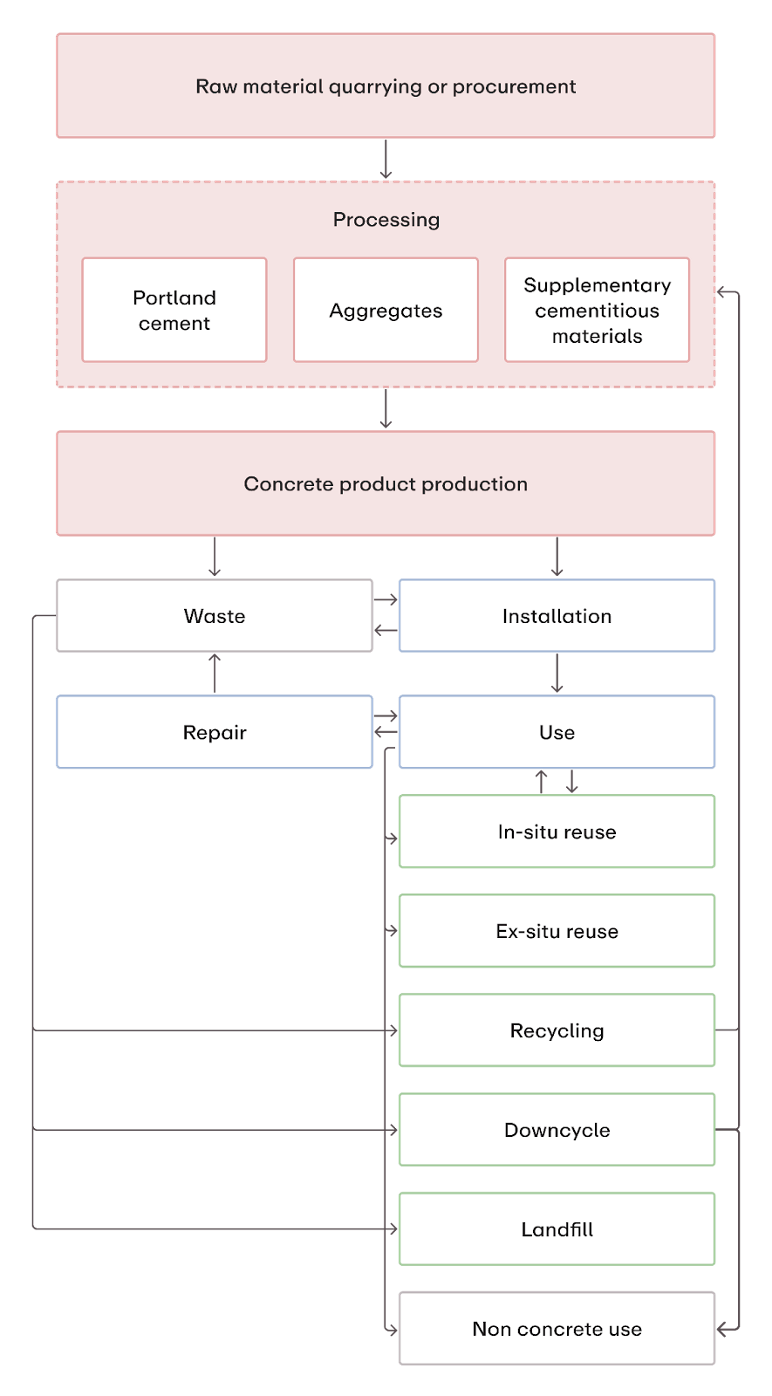
Figure 1. Stages of a concrete product, from materials extraction, through processing, use and end-of-life scenarios.
1. In-situ Reuse
In-situ reuse refers to extending the use of concrete in its original form. Some level of repair may be required. Because the concrete remains in its original form, it is not subjected to additional reversal risk and stored CO2 is considered stable.
2. Ex-situ Reuse
Ex-situ reuse refers to reuse of concrete in its original form, but in a different asset. This is uncommon practice for reinforced structural concrete elements due to the difficulty of extracting these components, lack of demand and the relatively low cost of new concrete. There are greater opportunities for ex-situ reuse with precast concrete elements, as these may be designed to facilitate deconstruction. There are currently limited regulatory frameworks worldwide that incentivize extensive re-use, though some examples do exist (see Norwegian Standard NS 3682). Frameworks currently under development will likely limit concrete reuse based on exposure class, potentially resulting in more extensive reuse of lower performance elements. Because the concrete remains in its original form, it is not subjected to additional reversal risk and stored CO2 is considered stable.
3. Closed-loop Recycling
Closed-loop recycling refers to waste processing that occurs in a closed loop, allowing the waste to retain its original value and return to the original production process. Technologies for concrete closed-loop recycling remain nascent and have not yet been deployed at scale. As such, the current likelihood that concrete will be recycled at end-of-life is very low. However, it is important to note that closed-loop recycling commonly involves high-temperature waste processing that will result in re-release of stored CO2.
4. Downcycling
Downcycling refers to waste processing where the resultant product has lower value than the original product. This is the most common end-state use case for concrete, occurring for approximately 90% of concrete and demolition waste in the UK16. This process typically involves crushing of concrete and subsequent use in applications such as road subbase, coastal defenses, engineering fill and external landscaping. Downcycled concrete may also be used as aggregate in new concrete products in instances where contamination from other waste products is low. Downcycling increases uncertainty about the location of CO2-storing concrete, but does not introduce any direct reversal risks.
5. Landfill
Concrete is landfilled when it cannot be effectively used in another application through reuse, closed-loop recycling or downcycling. Landfilled concrete can be assumed to remain within a single storage location for long timescales, decreasing geographical uncertainty. However, additional reversal risks may be introduced (e.g. acidic groundwater) depending on regional characteristics.
Applicability
This Module is applicable to Projects that store CO2 in the built environment by mineralizing CO2 removed from the atmosphere as carbonate minerals. This includes:
- Various carbonation technologies, such as:
- Carbon injection during mixing, or
- Carbon curing, or
- Carbon-sequestering aggregates or carbon-sequestering supplementary cementitious materials (SCMs), or
- Carbonation of concrete slurry wastewater
- Projects storing carbon in concrete, via one of the aforementioned technologies
- Projects using a CO2 source that constitutes a net removal from the atmosphere (e.g. Direct Air Capture, Direct Ocean Capture or Biogenic Carbon Capture and Storage)
- Carbonated concrete that meets the same performance requirements of a conventional product for the intended use case (see Section 7) and
- Carbonated concrete that does not require additional products or activities related to installation and maintenance, as compared to conventional products, with the exception of carbonation related technology and infrastructure
Projects that are explicitly not applicable include:
- Projects storing CO2 in the built environment in the form of biochar
- Projects storing CO2 in the built environment in lumber
- Projects storing CO2 using a technology not included in the above applicability criteria and/or
- Projects using a CO2 source that constitutes an Emission Avoidance
It is strongly recommended that all Projects provide documentation specific to the region of operations. This documentation may include, but is not limited to:
- Geologic maps of bedrock lithology (from USGS or national equivalent) and groundwater pH
- Climatic data, including average yearly temperature, precipitation volume and precipitation pH
- Estimated transport radius of produced materials
- If this is unknown for a given Project, Project Proponents may use either the maximum possible transport distance or a conservative average distance
- Types of assets that materials may be used in and a breakdown by percentage
- Proof of material suitability for the range of applications (e.g. certificates of compliance with concrete quality and performance standards)
- Risk of external acid attack, based on:
- Regional groundwater and precipitation pH.
- Likely exposure risk of the concrete containing stored carbon
- This can be determined through analysis of possible asset types and well-justified assumptions about the location of the concrete within the asset
- Probability analysis of concrete end-state based on regional trends
Any documentation that a Project Proponent is able to provide will be used to calculate a Project-specific reversal risk, as described in Sections 8 and 11.
System Boundaries
Activities that were already occurring and would continue to occur without The Project may be omitted from the system boundary of the Greenhouse Gas (GHG) accounting, if evidence that the activity was already occurring and would have continued to occur in the absence of the CO₂ storage activity can be provided.
Emissions associated with activities upstream and downstream of the CO₂ mineralization process that are separate to the mineralization process may be omitted from the system boundary if the carbonated concrete meets the same performance requirements as a conventional product for the intended use case, as set out in Section 3. Meeting the same performance requirements indicates that the product does not require additional activities related to product manufacturing, installation, maintenance and end-of-life, as compared to conventional concrete products. Emissions associated with concrete product manufacturing, installation, maintenance and end-of-life would have occurred anyway had a different concrete product been produced and used.
The exception to this rule is that additional information is required for exclusion of transport emissions, including transport of aggregates to a concrete batching plant and transport of concrete to a construction site. This is to negate the risk of induced transport associated with lower availability of novel carbonated concrete products and a demand for lower carbon construction materials. In order to exclude transport emissions from the system boundary, the Project Proponent must provide suitable justification that transport distances are expected to be within the bounds of national average aggregate and concrete transport distances.
Emissions associated with all activities and equipment related to the processing, temporary storage and mineralization of CO₂ in concrete must be fully accounted for within the Project's system boundary.
Emissions allocation procedures are set out in Section 5.2.3.
Quantification of CO₂eStored
Summary
This section details the calculation of net CO2 removal and storage in concrete. The monitoring requirements are described in detail in Section 6. Where carbonated materials are incorporated into concrete, Projects are subject to some additional monitoring requirements associated with pre-treated and carbonated feedstocks, including the geochemical and physical characteristics of carbonated feedstocks (Section 3, Section 5.3, Rock and Mineral Feedstock Characterization Module).
Accurate quantification of net CO2 removal requires a robust quantification of associated Project emissions within the Project boundary. In the context of this Module, a Project refers to the point of CO2 capture and the point of CO2 storage. This Module defines the point of CO2 storage as the point of carbonation related specifically to Project activities. For example, in a Project that injects CO2 during the curing process (carbonation curing) the point of storage would be after the concrete product is removed from the curing chamber and carbonation has been verified. In a Project that injects CO2 into cement during mixing, or a Project incorporating carbonated materials into concrete, the point of storage would be verification of carbonate content. This does not include carbonation that occurs as a result of environmental exposure under ambient conditions.
Projects are required to provide detailed descriptions of system boundaries for all crediting activities. Project boundaries must include all areas where removal mechanisms/processes may occur, removed carbon storage locations/forms and potential reversal/loss pathways.
Calculation of CO₂eRemoval
The quantity of net CO2 removal for each Reporting Period, RP, can be calculated as follows:
Equation 5
Where:
is the net quantity of CO2e removed as a result of Project activities during a Reporting Period, in tonnes of CO2e.
is the total quantity of inorganic carbon stored in the solid form during a Reporting Period, in tonnes of CO2e. This will be calculated differently according to the specific technology used to store the carbon within the concrete.
the total CO₂ removed from the atmosphere and permanently stored in the baseline scenario for a given RP, presented in tonnes CO₂e. This is the amount of inorganic carbon that would have been stored via carbonation regardless of the CO₂ storage process, over the lifetime of the Credit, either in a) a given feedstock as a result of natural weathering and b) from carbonation of concrete, in tonnes of CO₂e.
is the total quantity of greenhouse gas (GHG) emissions from Project activities for a Reporting Period, in tonnes of CO2e.
Calculation of CO₂eStored
Equation 6
Where:
is the difference in CO2 concentration in the influent gas stream and effluent gas stream, measured by sensors. Though the calculation hinges on measurements of influent and effluent CO2, these must be verified by direct measurements of carbonation; this is described further in Section 6.
is the amount of CO2 that is accumulated in the pores of the feedstock in tonnes CO2. As carbonates form from reaction of the feedstock with CO2, permeability is reduced, trapping CO2 within the pore volume. This trapped CO2 may then be released upon removal of the materials from the reactor. The volume of CO2 trapped in pore space can be conservatively estimated based on the density and bulk density of the feedstock and the measured concentration of CO2: This term is relevant only for Projects using indirect carbonation methods, as described in Section 2.1.2.
Equation 7
Where:
-
is the density of CO2 in the gas phase in tnCO2/m3:
-
(Equation 8)
- is the CO2 mole fraction;
- is pressure, in Pa;
- is the molar mass of CO2, in g/mol;
- is the gas constant, in J/molK;
- is temperature, in K
-
-
is the mass of feedstock in the reactor in tn;
-
is the bulk density of the feedstock in tn/m3feedstock;
-
is the porosity of the feedstock in m3pores/m3feedstock;
Calculation of CO₂eCounterfactual
is defined as:
Equation 9
Where:
is the amount of carbonation that would have occurred under business-as-usual practices over the concrete life cycle. Note that concrete life cycle refers to the full duration of time that the concrete element is exposed to the atmosphere. As the durability of CO2 in concrete is assumed to be 1,000 years in this Module, 1,000 years is the default timescale unless further information is provided. Such information may include the use case of the concrete in its initial life cycle and the probability of use cases in subsequent life cycles. In the built environment, business-as-usual refers to an equivalent asset (e.g., building, infrastructure, etc.) constructed with conventional concrete products. For calculating Counterfactual concrete carbonation, the life cycle of concrete is considered as the duration of exposure to conditions that may lead to carbonation; for instance, carbonation is considerably more likely to occur in facade elements than in concrete that has been landfilled following demolition.
There are limited studies on the effect of CO2 injection, carbonation curing and incorporation of carbonated materials on the rate of passive carbonation. Zhang & Shao (2016)17 found that early carbonation curing of concrete did not increase the rate of passive carbonation. Additionally, Rostami et al. (2012)12 found that carbonation curing decreased the permeability of concrete due to the decrease in calcium ions resulting from the carbonation process. Because passive carbonation is a diffusion-controlled process, reduced permeability of CO2-storing concrete may lead to a decrease in the passive carbonation rate. This is a key area for further research in the development of CO2-storing concrete technologies. Due to the lack of empirical data on changes to passive carbonation rate in CO2-storing concrete, this Module does not consider carbonation following Project activities as part of the quantification framework. This may be revisited as scientific consensus evolves.
is the amount of inorganic carbon that would have been stored in the aqueous or solid phase as a result of passive weathering of the carbon-sequestering aggregate or SCM used, without Project intervention, across a credit lifetime. Note that this term is only applicable for Projects using carbon-sequestering aggregates or SCMs, such as steel slag. In calculating , the default timescale assumption is 1,000 years if no additional information regarding the storage conditions and duration of the feedstock at the mine/quarry site can be provided. If additional information on the conditions and duration of feedstock storage at the feedstock supplier are available, Project Proponents may justify calculating the counterfactual across a time period relevant to the specific mine or quarry from which the feedstock is sourced in the PDD. For example, Projects operating in conjunction with active mines may find it appropriate to use the time of mine closure and provide details of the closure plan in the Project Design Document (PDD). Alternatively, if sufficient documentation exists suggesting that piles of waste materials generated by the feedstock will not be exposed to ambient environmental conditions such as encapsulation/capping, which would restrict further weathering, for a period exceeding a set number of years, the counterfactual may be considered across that time span.
It is important to note that studies have shown that the vast majority of weathering in tailings storage facilities (TSF) occur in the surface layers that are exposed to the atmosphere, provided that there is no physical manipulation18 19 20. For this reason, counterfactual weathering needs to be accounted for in the top meter of the tailings storage facility21.
must be calculated by modeling of expected carbonation rates under regional conditions. Models must take into account:
- Amount of concrete in contact with the atmosphere
- Asset type
- Regional climatic patterns, including:
- Average annual precipitation
- Precipitation pH
- Average relative humidity
- Average annual temperature
- Concrete composition
- Concrete porosity
- Carbonation rate
All numbers used in these models should be sourced from reliable databases, which may be publicly available or maintained by industrial stakeholders. Where appropriate data is available, Project Proponents may choose to substitute values for counterfactual concrete carbonation that are sourced from peer-reviewed literature or public databases for model-based methods.
must be calculated by a combination of direct measurements and modeling of the expected weathering rate of feedstock under storage conditions relevant to the source site for either 1,000 years or a time period justified in the PDD as described above. Models must be justified by empirical data from subsamples of the feedstock; guidelines for sampling procedures that adequately capture feedstock heterogeneity are described in the Rock and Mineral Feedstock Characterization Module. Models must take into account:
- Feedstock mineralogy (direct measurement)
- Feedstock surface area (direct measurement)
- Baseline carbonation of the tailings pile (direct measurement)
- CDR potential of the tailings pile in the top 1 m (calculated from direct measurements)
- Environmental conditions of the source site (direct measurement or publicly available data), including:
- Temperature
- Average yearly precipitation
- Rainwater pH
- Groundwater pH
- Carbonate saturation
- Permeability (direct measurement or calculated from direct measurement)
- Water saturation (direct measurement or calculated from direct measurement)
- Microbial activity (direct measurement)
The measurements and model used to calculate CO2eCounterfactual must be provided to Isometric and the Validation and Verification Bodies (VVB). Project Proponents may choose to either assume the total counterfactual as a one-time deduction or to spread the counterfactual deduction across the Project lifetime.
Calculation of CO₂eEmissions
CO2eEmissions is the total GHG emissions associated with a given Reporting Period, RP.
Equations and emissions calculation requirements for CO2eEmissions, including emissions associated with reactor operations and reaction monitoring, are set out in the relevant Protocol and are not included in this Module. Specific considerations for CO₂ stored in built materials are set out here.
As set out in Section 4, emissions associated with activities upstream and downstream of the CO₂ mineralization process that are separate to the mineralization process may be omitted from the system boundary if the carbonated concrete meets the same performance requirements as a conventional product for the intended use case. Emissions allocation procedures to separate emissions associated with the concrete production and the emissions associated with the CO₂ mineralization process must follow either:
- Procedure 1: Allocate all emissions to CDR
Projects may opt to allocate all Project emissions to CDR. The concrete product must still comply with all relevant emission accounting regulations and requirements, which may mean CO2eEmissions are double counted. This is the most conservative approach to take.
Or
- Procedure 2: Divide the process into sub-processes
Where possible, the process may be divided into sub-processes. For example it may be possible to isolate processes relating to processing, temporary storage and mineralization of CO₂ only, or the CO₂ mineralization process may be a retrofit to an existing facility. Sub-processes that are physically separable and do not contribute to CDR may be excluded from the CDR system boundary. Eligibility Criteria is provided in Table 2. If either EC1 or EC2 are complied with, it is acceptable to undertake procedure 2.
Table 2. Procedure 2 Eligibility Criteria, EC1 and EC2
Criteria | Description | Documentation required |
|---|---|---|
EC1 | The CO₂ mineralization process is a retrofit to an existing facility that was operable prior to the introduction of the mineralization process. The purpose of the existing facility must not have been related to carbon dioxide removal prior to retrofit. | Records of existing facility activities dating back 3 years must be provided for major infrastructure projects where a planning application was required. For all other projects, records of the existing facility activities dating back 6 months is required. The distinction between major infrastructure projects and other projects is to ensure that the CO₂ mineralization process is a retrofit, as major infrastructure project construction may be staged over many years. |
EC2 | The process has components and operations that are physically separate from one another. | Evidence of separation, for example engineering diagrams showing separate equipment or electricity metering systems for separate components of the process. Sub-processes that can be isolated from the CO₂ mineralization process and do not contribute to CDR may be excluded from the system boundary. |
CO2eStored must not be double counted, regardless of the production of product Environmental Product Declarations. The concrete product must still comply with all relevant emission accounting regulations and requirements, which may mean CO2eEmissions are double counted (once for CDR and once for EPD compliance where required), however removals (CO2eStored) must not be double counted in the EPD and may only be reported as part of Crediting for CDR. This is the most conservative approach to take. Crediting claims must be transparently reported and must not form part of marketing for a separate product. The concrete product must not be marketed as carbon negative if the product is used as a storage mechanism for the generation of Credits.
CO2eLeakage includes emissions associated with a Project's impact on activities that fall outside of the system boundary of a Project. It includes increases in GHG emissions as a result of the Project displacing emissions or causing a knock on effect that increases emissions elsewhere. Emissions reductions associated with the Project's impact on activities that fall outside the system boundary of a Project are not considered as part of CO2eLeakage . For built materials, CO2eLeakage may occur if the decision to procure a carbonated concrete for use in a built asset leads to an increase in emissions elsewhere on the Project, for example using more steel to make up for a reduction in structural strength. This is managed through the requirement to evidence that the carbonated concrete meets the same performance requirements of a conventional product for the intended use case.
Carbonation Monitoring Requirements
This section details the monitoring requirements for Projects utilizing carbonation curing, injection during mixing or incorporating carbonated materials into concrete.
System Requirements
Project Proponents are required to provide detailed information on the carbonation process. This includes:
- Reactor description and engineering design diagrams (described in further detail in sections 6.1.1-6.1.5).
- Concentration of CO2 stream (described in further detail in Section 6.2).
- Flow rate of the injection stream (described in further detail in Section 6.2).
Note: Project Proponents using carbonated materials incorporated into concrete are subject to additional system requirements, described in Section 6.3.
Reactor Type
Any type of engineered chemical reactor is eligible under the Module, provided that the reactor design requirements set out in Sections 6.1.2-6.1.5 below are satisfied. Acceptable reactor types include, but are not limited to, stirred tanks (either batch, semi-batch or continuous) and tubular reactors (plug flow, fixed bed, fluidized bed, bubble bed or trickle bed). This list is meant to be comprehensive, but not exhaustive. A brief overview of common reactor types covered under this Module is provided in Table 3. Novel reactor designs not belonging to any of the categories listed here will be acceptable provided that the appropriate reactor design documentation, according to Section 6.1.2, is supplied in the PDD. All reactor designs, including the reactor type, engineering design diagrams, reactor modeling calculations and materials selection must be described in the PDD.
| Reactor Category | Reactor Type | Description |
|---|---|---|
| Stirred tank | Batch | A closed well-mixed batch system where reactants are added to the vessel at the start of the batch, and products are removed from the vessel at the end of the batch. Mixing is provided by stirring with an agitator. |
| Semi-batch | A well-mixed batch system where reactants are added to the vessel at the beginning of the batch, and products are removed at the end of the batch. Reactants and/or products may be added/removed from the vessel over time throughout the batch. Mixing is provided by stirring with an agitator. | |
| Continuous | An open well-mixed system where reactants and products are both added/removed from the vessel continuously. Mixing is provided by stirring with an agitator. | |
| Tubular | Plug flow | A simple open tubular reactor where reactants flow through the vessel and chemical reaction occurs along the length of the vessel. |
| Fixed bed | An open tubular multiphase reactor where reactants flow over a fixed packed bed of solid reactive material. Chemical reaction occurs along the length of the vessel. | |
| Fluidized bed | An open tubular multiphase reactor where reactants fluidize a bed of solid reactive material. Fluid reactants and solid material flow co-currently within the vessel. Chemical reaction occurs along the length of the vessel. | |
| Bubble bed | An open tubular multiphase reactor where gaseous reactants flow in a vessel saturated with liquid. The gaseous species migrate through the column as bubbles of gas. Chemical reaction occurs along the length of the vessel. | |
| Trickle bed | An open tubular multiphase reactor where liquid reactants flow downwards over a packed bed of reactive solids, while gaseous species flow upwards. Chemical reaction occurs along the length of the vessel. |
Table 3. Reactor type overview
Design Diagram Requirements
An engineering design diagram of the chemical reactor must be included in the PDD. The design diagram must include details of the dimensions of the reactor, the locations of material inflows/outflows, the positioning of sensors for the monitoring of flow rate, reactant/product chemical composition, temperature and pressure, details of any internal equipment such as agitators or heating/cooling coils and details of any external heat transfer equipment (including heat exchange fluid entry/exit points and corresponding sensors for flow rate and temperature). A sufficient number of viewpoints must be included in the engineering design diagram to show the positioning of all of the key components listed above. Any other process equipment essential to the safe and effective operation of the reactor not listed above should be included and highlighted in the engineering design diagram.
CO₂ and Feedstock Loss
The reactor design must include sensors necessary to quantify any loss of CO2 from the feedstock during operation of the reactor to leakage. This should include, at minimum, sensors to determine the inflow/outflow of CO2 from the reactor, which can be used in conjunction with a suitable reactor model to determine the amount of CO2 reacted and to estimate any loss of CO2 to leakage. Only CO2 which has been determined by this calculation to have undergone complete chemical reaction into a solid mineral product is eligible for carbon Credits issued under this Module.
In addition to loss of CO2 from the reactor, Project Proponents should consider the possibility of rock or mineral feedstock loss from the reactor in applicable systems. For example, in a packed bed or fluidized bed reactor using CO2 dissolved in liquid, it is necessary to set flow rates such that loss of solid feedstock particles from the system is minimized. Projects using reactors in which this is a risk are required to characterize solid feedstock loss.
The chemical reactor model used to characterize reactor performance and estimate CO2 and solid feedstock losses should consider all physical and chemical mechanisms relevant to operation of the chosen reactor type. The chemical reactor model should incorporate a chemical kinetics model which is based on the latest scientific understanding for the chosen chemical reaction pathway. Where chemical kinetics are derived from in-house experimental measurements, details of the experimental procedure used to perform these measurements should be included in the PDD.
Construction Considerations
Suitable mass/volume flow meters must be placed on all material inlets/outlets from the reactor to allow for characterization of reactor performance and to monitor any material losses to the environment. These sensors should be positioned immediately upstream/downstream of the reactor, as appropriate. Suitable sensors to measure pressure, temperature and pH (if applicable) should be implemented to allow for accurate characterisation of the reactor performance through a combination of measurements and modeling. For stirred tank reactor types, these sensors should be placed so that they accurately characterize the measured property in the bulk phase of the reactor. For tubular reactors, two (or more) measurements of each property at different locations may be necessary to accurately characterize the reactor performance. In this case, several sensors should be placed along the length of the reactor. Justification for the positioning of such sensors for characterization of reactor performance should be provided in the PDD.
It is anticipated that, for projects incorporating carbonated materials into concrete, operation of the chemical reactor may occur at high temperature and pressure, and that the pH inside the reactor may be acidic. Appropriate considerations need to be made in the design of the reactor to mitigate these operational conditions to ensure operational loss prevention. Details must be provided in the PDD to describe the selection of materials for each component of the reactor, including suitable justification for these choices from the perspectives of heat and corrosion resistance. For reactors operating at high pressures, considerations should be made relating to the operating pressure, vessel shape/size, positioning of material inlets/outlets, and positioning of sensors to ensure mechanical integrity of the reaction vessel. Such considerations should be made in compliance with a suitable local standard which provides regulations for the design and fabrication of pressure vessels, such as 2014/68/EU (the “Pressure Equipment Directive”) or an appropriate regional equivalent standard in the region of operation. If no such regional standard exists in the area of operation, Project Proponents are required to use the 2014/68/EU standard.
Reactor Maintenance
An appropriate reactor maintenance plan should be in place, and must be detailed in the PDD. The maintenance plan should outline how the Project Proponent will ensure the structural integrity of the reactor vessel to mitigate against potential material loss events. This includes suitable monitoring and mitigation for mechanical, thermal and corrosive events which may lead to failure of the vessel and subsequent release of reaction materials into the environment. All maintenance plans should be in compliance with a suitable local standard which provides regulations for the maintenance of pressure vessels, such as 2014/68/EU or an appropriate regional equivalent standard in the region of operation.
Concrete Characterization and Determination of CO₂ Stored
All Project Proponents are required to report the mass of CO2 that is mineralized in concrete. This should be determined by direct measurement of concrete samples. Project Proponents are required to ensure that sampling plans are representative of any variability that may occur as a result of the carbonation process; guidance on designing a representative sampling plan is given in the Rock and Mineral Feedstock Characterization Module.
Determination of CO2 stored in concrete must include the following analyses:
-
CO2 uptake during the reaction:
- CO2 concentration in inflow and outflow. Concentration must be:
- Measured immediately upstream of the point of introduction to the reactor; and
- Measured using a continuous inline analyzer, such as NDIR, TDL, or similar, which satisfies the below requirements:
- Must have an accuracy of 5% of full scale or better
- Recorded at a frequency of 1-minute intervals at minimum
- Calibrated in accordance with and at a frequency which meets or exceeds manufacturer calibration requirements, but which in any case must be no less than annual
- Calibration gasses must be traceable to national standards and a certificate of analysis indicating so must be available and
- Raw data must be made available upon request by the project VVB or Isometric
- Flow rate of the injection stream. Gas flow rate must be:
- Measured immediately upstream of the point of introduction to the reactor; and
- Measured using a continuous inline meter, such as a coriolis meter, thermal mass meter, or similar, which satisfies the below requirements:
- Provided with a factory calibration for the specific gas composition range expected.
- Meter accuracy specification of 2% full scale.
- Recorded at a minimum frequency of 1-minute intervals.
- Calibrated in accordance with and at a frequency which meets or exceeds manufacturer calibration requirements, but which in any case must be no less than annual;
- Calibration traceable to national standards
- Meters are selected and installed for the expected and observed operating range of the emitted stream.
- Meters are installed in accordance with manufacture installation guidelines, including, for example, minimum distances up or downstream of piping disturbances required to ensure accurate flow measurement; and
- Raw data must be made available upon request by the project VVB or Isometric.
- Provided with a factory calibration for the specific gas composition range expected.
- CO2 concentration in inflow and outflow. Concentration must be:
-
Total carbon (TC) and total inorganic carbon (TIC) of concrete samples. Measurements should be made within 24 hours of exiting the reactor to ensure minimal natural carbonation (counterfactual) has occured. Acceptable measurement methods include thermogravimetric analysis coupled with mass spectrometry (TGA-MS) and dry combustion. Alternate measurement methods may be proposed and must be described in detail and justified in the PDD. The following requirements must be satisfied:
- Calibration and standard data must be provided alongside sample measurements;
- Raw data must be made available upon request by the project VVB or Isometric; and
- Validation checks of TC and TIC of concrete samples must be completed quarterly for each concrete mix used.
It is strongly recommended that Project Proponents perform mineralogical characterization measurements on concrete samples to determine the phase of carbonate minerals present. This informs reversal risk associated with high temperatures, as described in Section 8.1 and may be considered as part of a Buffer Pool Assessment (Section 8.2).
All methods used must comply with international or regional standards where applicable (e.g. ISO, EN, ASTM); where standard methods are unavailable, the standard operating procedures (SOP) used must be submitted in the PDD. Further detail on rock characterization can be found in the Rock and Mineral Feedstock Characterization Module.
Option for Carbonation Quantification Using Single-Phase Measurements
Project Proponents may choose to omit direct measurements of concrete samples and quantify using only gas measurements where sufficient evidence can be provided that carbonate minerals are the only possible CO2 sink within the carbonation system. Such proof must include:
-
Mass balance calculations over the reactor system, including measurements and kinetic reactor modeling;
-
Continuous measurement of system pressure. Pressure sensors must comply with the following requirements:
- Must have an accuracy of 2% of full scale or better;
- Recorded at a minimum frequency of 1-minute intervals;
- Calibrated in accordance with and at a frequency which meets or exceeds manufacturer calibration requirements, but which in any case must be no less than annual;
- Raw data must be available upon request.
-
Regular leakage testing of the system. Leakage testing should be conducted according to prevailing national/international standards, and/or by an accredited leakage testing authority, for example in compliance with ASTM E1003-13(2022), or an equivalent standard. Leakage testing should be conducted at least once every 12 months. Project Proponents are required to maintain proof and results of leakage tests for a period of at least five years.
Baseline Characterization for Direct Concrete Carbonation Projects
Projects using a direct carbonation approach (e.g. carbonation curing or CO2 injection during mixing) are required to characterize any carbonates that are present in the concrete components prior to the commencement of Project activities. This can be conducted as either a) the sum of CO2 from measurements of discrete components, or b) measurement of CO2 in the concrete mix prior to carbonation. Measurement methods must be the same as those used for determination of CO2 stored post-carbonation (measurement of TC and TIC by TGA or equivalent). It is strongly recommended to assess the mineralogy of the concrete prior to carbonation via XRD.
Note that, in the event that a Project Proponent provides sufficient evidence to warrant a single-phase quantification technique, baseline characterization of concrete is recommended but not required.
Additional Requirements for Carbonated Materials Incorporated into Concrete
Projects using carbonated materials incorporated into concrete are required to follow the requirements described in the CO2 Storage via Ex-Situ Mineralization in Closed Engineered Systems Module. This includes:
- Section 2.0: System Requirements.
- Section 3.0: Feedstock Characterization and Pre-Treatment (see also Rock and Mineral Feedstock Characterization Module).
- Section 5.0: Monitoring Requirements.
In addition to requirements associated with carbonation of the feedstock, Project Proponents are required to provide proof that the carbonated materials are incorporated into concrete. This includes:
- Proof or declaration of sales to a concrete producer; and
- List of products produced using the carbonated materials.
Compliance with Concrete Standards
An applicability criteria for crediting with this Module is that the carbonated concrete must meet the same performance requirements as conventional concrete products for the intended use case. Project Proponents are required to demonstrate compliance with the relevant standards for the use case of each concrete mix produced, while also demonstrating the carbonated concrete is comparable to traditional concrete (such as Portland cement) and results in no additional cement use. It is the responsibility of the Project Proponent to demonstrate comparability between produced concretes and traditional concretes within the PDD submitted to the project VVB and Isometric. Standards, methodologies and SOP’s that are utilized by a Project Proponent must be clearly outlined and referenced in the PDD upon submission, and deviations from standards must be highlighted.
Concretes produced for the purpose of carbon storage and credit issuance are expected to meet the same performance standards and criteria as traditional concrete products that would have been used in the absence of the carbonated concrete material. This may be achieved through the undertaking of standardized performance testing procedures required in the location the material is utilized. In the absence of local or regional standards related to concrete production and performance criterias, a Project Proponent is required to adhere to International Organization for Standardization (ISO) criteria.
Reversal Risk
Overview of Reversal Risks
The two primary pathways by which CO2 can be lost from carbonate minerals are exposure to high temperatures (e.g., >300 °C 22) and contact with low pH fluids. These conditions, though not necessarily common globally, can occur in some instances; for example, temperatures in a building fire can reach up to 1200 °C (European Union Decision 2008/163/EC) and the pH of groundwater that is impacted by industrial pollution (e.g. acid mine drainage (AMD) ) can be below 323.
Carbon loss resulting from high temperatures is referred to as calcination and occurs by the reaction:
Equation 10
The kinetics of this reaction are strongly dependent on both temperature and crystal structure17. Multiple polymorphs of CaCO3 exist in nature, the most common of which is calcite. Studies have shown that, depending on the reaction conditions, calcination of calcite can occur between 680 - 900°C24. Other possible CaCO3 polymorphs include aragonite and vaterite, both of which decompose at lower temperatures than calcite (450 - 725°C 17). Depending on the feedstock mineralogy, magnesium carbonates may also be present, which can decompose at temperatures as low as 300 °C25. Thus, conservative estimates of carbon loss due to calcination require either detailed carbonate mineralogy data or the assumption that at least some of the CaCO3 present is in non-calcite carbonate phases.
Carbon loss resulting from contact with low pH fluids is dependent on a) pH, b) the acid source, c) ambient temperature, d) concrete's initial composition and porosity, and e) length of exposure. In particular, interaction of carbonate minerals with strong acids, such as sulfuric, nitric or phosphoric acid, lead to release of CO2 following the reactions:
Equation 11
Equation 12
Equation 13
Conversely, where the acid source is carbonic acid, interaction with calcium carbonates can result in either carbon loss or carbon storage depending on the pH of the solution. Dissolution of CaCO3 by carbonic acid (here represented as CO2 + H2O) occurs following the reaction:
Equation 14
In this reaction, dissolution of 1 mole of CaCO3 results in the capture of 1 mole of CO2 as bicarbonate (HCO3-). Bicarbonate is part of the carbonic acid system, the speciation of which is highly pH-dependent26. As pH decreases, the relative concentration of dissolved CO2 increases. This dissolved CO2 can exchange with the atmosphere, resulting in a release of CO2. Further information can be found in references 27 28 29.
Accurate carbon accounting for CO2 stored in the built environment requires consideration of possible reversal risks in the life cycle of concrete, particularly because in the vast majority of cases reversals will not be directly observable and uncertainty in storage site (see Section 8.1.1) increases with time due to asset demolition and subsequent use of demolished concrete (see Section 2.2). This section details the approach that this Module takes to quantifying reversal risk.
Definition of Storage Uncertainty
A key consideration for the durability of CO2 stored in concrete is not only exposure to conditions in which a reversal event is likely to occur, but also the uncertainty in the location of the concrete at any given time. As described in Section 2.2, concrete may go through many different use cases in its life cycle, depending on the initial use case, local regulatory requirements and economic incentives. In the traditional concrete industry, there has not been a need to track concrete past the life cycle of an asset, particularly where elements are designed to perform with minimal maintenance or intervention. Thus, CO2-storing concrete is likely to transition through several construction-demolition-reuse cycles with minimal ability to track these changes. Over long time periods (e.g. 1,000 years), this leads to a high degree of uncertainty in both the storage location of the concrete and, consequently, whether or not the concrete is exposed to conditions that lead to release of CO2. This necessitates a conservative approach to reversal risk, described in the following section.
Reversal Risk Approach
Quantifying the risk of reversal associated with CO₂ storage via carbonation in built materials is inherently complex, given the high degree of uncertainty and variability in possible end-states of the built materials over 1,000 years. Reversal may occur when the built material is in a ‘use case’ (e.g. as part of a building), or when the built material goes through an end-of-life transition (e.g. recycled). Specifically for built materials, the following reversal risk conditions have been identified which may lead to reversal.
Exposure to the following when the built material is in a use case (e.g. as part of a building):
- Acid rain
- Acidic groundwater/ soils
- High temperatures e.g. as a result of house fires/ forest fires
Exposure to the following when built material goes through an end-of-life transition:
- High temperatures as a result of closed-loop recycling where concrete is changed back to clinker (‘Closed-loop Recycling’)
Though closed-loop recycling constitutes a complete reversal of CO2 storage, the likelihood of this occurring is currently extremely low due to the nascency of the technology. At the time of drafting, there are a limited number of pilot projects operating at small scale, including in the United Kingdom, France and Canada. As closed-loop recycling is not currently operating at scale, it has been excluded from the calculation of reversal risk at this time. However, it is important to note that closed-loop recycling, if included in the reversal risk model, has a significant impact on the total reversal risk (see Appendix 1, Figure A1.2 for details). The inclusion of closed loop recycling in the reversal risk model will be revisited regularly as data availability increases and technologies develop.
An additional consideration for the scaling of closed-loop recycling technology is the co-evolution of carbon capture and storage (CCS) technology, which could re-capture emitted CO2 from closed-loop recycling on concrete if the technologies are co-deployed. Current recommendations for decarbonization of the cement industry include point-source capture of CO2 from cement plants30, and several companies in the industry are investing in the development of CCS technology31. As both closed-loop recycling and CCS technologies scale, revisiting reversal risks associated with closed-loop recycling will also include assessment of the likelihood of co-deployment with CCS.
In order to quantify reversal risks over multiple use cases and multiple end-of-life transitions, this Module utilizes a reversal risk model, described in detail in Appendix 1. The aim is to model reversal risk over time to inform the following:
- Parameters that have the most significant impact on risk of reversal
- Uncertainty discount designation
- Applicability criteria
The reversal risk model tracks the amount of carbon in the following reservoirs: built materials (i.e. in a use case), landfills and the atmosphere. The model considers flows of carbon between these reservoirs due to different end-of-life transitions, as well as reversals from exposure to acidic water and high temperatures. Predicting future states of the built material is highly uncertain (see Section 8.1.1), so the approach taken here is to define a conservative scenario, which would give a larger reversal risk. Key assumptions made for this conservative scenario are:
- Worst case scenarios for reversals due to acid rain and contact with acidic ground waters, of 5% over 1,000 years
- Building fires results in complete reversal of the CO2 stored in the built materials
- A lifespan of 25 years for all use cases
See Appendix 1, Table A1.1 for more details and justification of these and other assumptions, as well as more discussion on sensitivity tests and findings from the model.
The results of running the reversal risk model with this conservative scenario are shown in Appendix 1, Figure 2. The model starts at year 0 with 100% of the CO2 stored in a use case (red line). As the model steps forward in time, the amount of CO2 stored in the use case decreases, while the storage in landfill (blue line) and emissions to the atmosphere (green line) increases. After 1,000 years, the total CO2 that remains stored out of contact of the atmosphere is approximately 94% (orange line). This is a combination of storage in a use case and storage in a landfill. The average reversal risk at 1,000 years is approximately 6% (green line), i.e. 6% of the CO2 initially stored in a use case is re-released to the atmosphere.
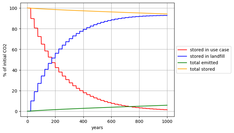
Figure 2. The average expected percentage of carbon stored in built materials, landfill, and emitted to the atmosphere over 1,000 years given a conservative scenario with the assumptions described in Section 8.2 and Appendix 1, Table A1.1. The total amount of CO2 emitted after 1,000 years is used to inform the Uncertainty Discount strategy (Section 8.3).
Uncertainty Discounts
Uncertainty Discounting is an approach used to reduce the amount of Credits that can be issued, to account for uncertainty in CO2 removal and storage, particularly in instances where reversals cannot be monitored or observed. In instances where the CO2 storage can not be readily monitored for and attributed to a particular project (e.g. storage in open system reservoirs such the ocean), then the storage uncertainty is typically accounted for as a reduction to the number of Credits issued.
Based on the results of the reversal risk model for a conservative scenario (Section 8.2), it is required that Project Proponents seeking Credits with a 1,000 year durability deduct a 6% loss on to account for reversal risks. Where additional information that may reduce uncertainty around reversal risk is available, Project Proponents may submit documentation (such as those recommended in Section 3.0) to include in a Uncertainty Discount Assessment, which will include project-specific model determination of reversal risk using submitted data.
Acknowledgements
Isometric would like to thank following contributors to this Module:
- Emily Walport, Lucy Caine, Grace Di Benedetto, Stephen Thompson, and Helene Gosden (Arup) with the support of Arup's global specialists; whose technical report on the practical applications of concrete in the built environment and the impacts to durability of stored CO2 informed this Module. Isometric has utilized elements of Arup’s report to form the foundation of this Module.
- Maciej Jozwik; whose technical report Assessment of carbon dioxide stability in post-demolition carbonated concrete informed the development of this Module and reversal risk approach.
- Xueya Lu (University of British Columbia); whose geochemical reversal risk modeling, and subsequent report, informed Isometric's reversal risk determinations within this Module.
Definitions and Acronyms
- ActivityThe steps of a Project Proponent’s Removal process that result in carbon fluxes. The carbon flux associated with an activity is a component of the Project Proponent’s Protocol.
- BaselineA set of data describing pre-intervention or control conditions to be used as a reference scenario for comparison.
- Buffer PoolA common and recognized insurance mechanism among Registries allowing Credits to be set aside (in this case by Isometric) to compensate for Reversals which may occur in the future.
- Carbon Dioxide Removal (CDR)Activities that remove carbon dioxide (CO₂) from the atmosphere and store it in products or geological, terrestrial, and oceanic Reservoirs. CDR includes the enhancement of biological or geochemical sinks and direct air capture (DAC) and storage, but excludes natural CO₂ uptake not directly caused by human intervention.
- CounterfactualAn assessment of what would have happened in the absence of a particular intervention – i.e., assuming the Baseline scenario.
- CreditA publicly visible uniquely identifiable Credit Certificate Issued by a Registry that gives the owner of the Credit the right to account for one net metric tonne of Verified CO₂e Removal. In the case of this Standard, the net tonne of CO₂e Removal comes from a Project Validated against a Certified Protocol.
- DurabilityThe amount of time carbon removed from the atmosphere by an intervention – for example, a CDR project – is expected to reside in a given Reservoir, taking into account both physical risks and socioeconomic constructs (such as contracts) to protect the Reservoir in question.
- Emission AvoidanceAvoiding future GHG releases from a specific entity.
- FeedstockRaw material which is used for CO₂ Removal.
- Greenhouse Gas (GHG)Those gaseous constituents of the atmosphere, both natural and anthropogenic (human-caused), that absorb and emit radiation at specific wavelengths within the spectrum of terrestrial radiation emitted by the Earth’s surface, by the atmosphere itself, and by clouds. This property causes the greenhouse effect, whereby heat is trapped in Earth’s atmosphere (CDR Primer, 2022).
- LeakageThe increase in GHG emissions outside the geographic or temporal boundary of a project that results from that project's activities.
- Lossesfor open systems, biogeochemical and/or physical interactions which occur during the removal process that decrease the CO₂ removal .
- ModelA calculation, series of calculations or simulations that use input variables in order to generate values for variables of interest that are not directly measured.
- ModuleIndependent components of Isometric Certified Protocols which are transferable between and applicable to different Protocols.
- ProjectAn activity or process or group of activities or processes that alter the condition of a Baseline and leads to Removals.
- Project Design Document (PDD)The document that clearly outlines how a Project will generate rigorously quantifiable Additional high-quality Removals.
- Project ProponentThe organization that develops and/or has overall legal ownership or control of a Removal Project.
- ProtocolA document that describes how to quantitatively assess the net amount of CO₂ removed by a process. To Isometric, a Protocol is specific to a Project Proponent's process and comprised of Modules representing the Carbon Fluxes involved in the CDR process. A Protocol measures the full carbon impact of a process against the Baseline of it not occurring.
- RemovalThe term used to represent the CO₂ taken out of the atmosphere as a result of a CDR process.
- ReservoirA location where carbon is stored. This can be via physical barriers (such as geological formations) or through partitioning based on chemical or biological processes (such as mineralization or photosynthesis).
- ReversalThe escape of CO₂ to the atmosphere after it has been stored, and after a Credit has been Issued. A Reversal is classified as avoidable if a Project Proponent has influence or control over it and it likely could have been averted through application of reasonable risk mitigation measures. Any other Reversals will be classified as unavoidable.
- Sensitivity AnalysisAn analysis of how much different components in a Model contribute to the overall Uncertainty.
- SinkAny process, activity, or mechanism that removes a greenhouse gas, a precursor to a greenhouse gas, or an aerosol from the atmosphere.
- SourceAny process or activity that releases a greenhouse gas, an aerosol, or a precursor of a greenhouse gas into the atmosphere.
- StakeholderAny person or entity who can potentially affect or be affected by Isometric or an individual Project activity.
- StorageDescribes the addition of carbon dioxide removed from the atmosphere to a reservoir, which serves as its ultimate destination. This is also referred to as “sequestration”.
- System BoundaryGHG sources, sinks and reservoirs (SSRs) associated with the project boundary and included in the GHG Statement.
- UncertaintyA lack of knowledge of the exact amount of CO₂ removed by a particular process, Uncertainty may be quantified using probability distributions, confidence intervals, or variance estimates.
- Asset - Any tangible or intangible property that has value and can be owned, controlled or utilized by an individual or organization. In the context of this Module, an asset refers to a physical structure.
- Built Material - A material used in the construction of an asset.
- Concrete - A composite material composed of aggregate, cement, sand and water that cures to a solid over time.
- Cement - A chemical substance used for construction that sets, hardens, and adheres to other materials to bind them together. Ordinary Portland Cement (PC) is the most common cement used in modern concrete. Other types of cement include Ground Granulated Blast-furnace Slag (GGBS), Pulverised Fly Ash (PFA) and natural pozzolans.
- DAC - Direct Air Capture.
- DOC - Direct Ocean Capture.
- Durability - The amount of time carbon removed from the atmosphere by an intervention – for example, a CDR project – is expected to reside in a given Reservoir, taking into account both physical risks and socioeconomic constructs (such as contracts) to protect the Reservoir in question (Isometric Standard).
- Aggregate - The inert (inactive) granular material that makes up a large portion, typically 60% to 80%, of concrete by volume. It acts as a filler and helps provide strength and improve workability.
- Built Environment - “Man-made structures and facilities used to accommodate societies’ activities. Any enclosures, spaces, structures, and infrastructure formed to convert the natural environment into a habitable and useable area for the purpose of living, working, and playing” (Ref).
- Tailings - Finely ground rock of low residual value from which valuable minerals have been extracted. Tailings are a by-product produced following mineral processing of ore. Tailings are usually homogenous in both particle size and geochemical composition.
- Technology Readiness Level – a method for assessing the maturity of a technology, determined using a Technology Readiness Assessment that examines program concepts, technology requirements and demonstrated technology capabilities.
- Polymorph – minerals with the same chemical composition but different crystal structure.
- Design life – period of time for which a built asset is designed to function.
- Functional service life – period of time for which a built asset is actually in service; may differ from design life based on a variety of factors.
Appendix 1: Reversal Risk Determination
Model Description
The Reversal Risk over 1,000 years was assessed by developing a simple model that tracks the amount of carbon stored in different reservoirs over time. The model accounts for the following reservoirs: the atmosphere, landfill, and up to three different use cases.
The model is initialized with 100t of CO2 stored in an initial use case, and 0 in the other reservoirs, so that the results can be interpreted in terms of percentages. The model steps forward in time for 1,000 years, with a timestep of 1 year. Each year, carbon is exchanged between the use case reservoirs and the atmosphere, and between the landfill and atmosphere to represent reversal risks as a result of exposure to low pH waters and high temperatures. When the lifespan of a use case is reached, the carbon stored in the use case undergoes transitions where it is reallocated to different reservoirs. Figure A1.1 shows a schematic of the reservoirs and flows of carbon in the model for the simplified scenario when there is only one use case, which is sufficient for constraining the bounds of reversal risk.
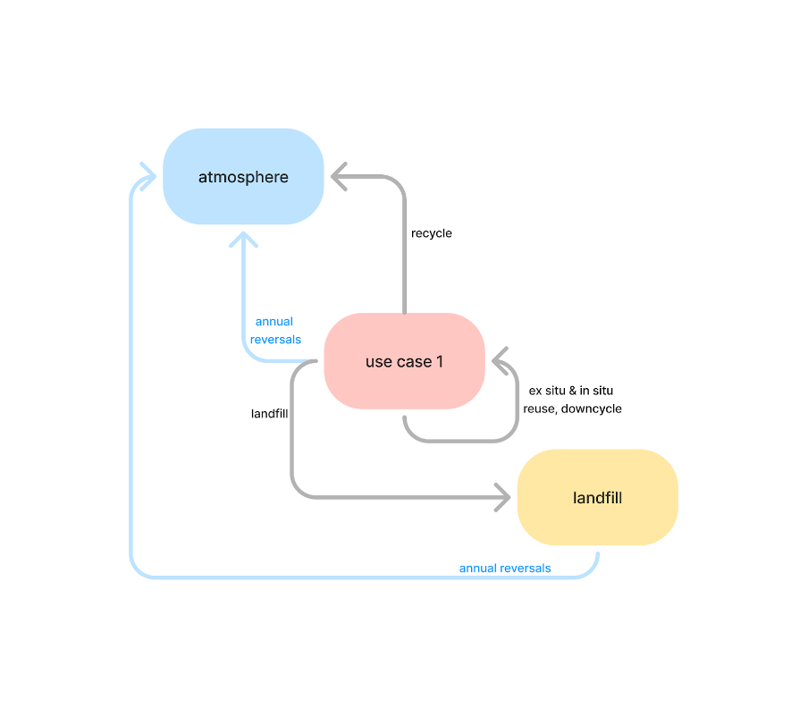
Figure A1.1. Schematic of reservoirs and flows of carbon in the model in the scenario where there is only one use case. Blue arrows denote annual reversals of CO2 emitted to the atmosphere, while gray arrows denote different end-of-life transitions that can occur at the end of the use case’s life span.
A number of assumptions have been made for various parameters in the model, which are described in Table A1.1.
Table A1.1. Table of model parameters. See Section 2.2 for more information on a Project Lifecycle and each of the parameters.
| Parameter Name | Description | Default value | Justification |
|---|---|---|---|
| lifespan | Lifespan of Use Case | 25 years | Lifespan assumption, based on Section 2.2. Even though downcycling will likely result in infrastructure with a longer design life of ~100 years, we take a shorter assumption on the life span because the functional service life is typically much shorter than the design life. |
| closed-loop recycle | Probability of closed-loop recycling occurring as an end-state use case | 0% | Closed-loop recycling techniques for concrete are still at the very early stages of development with some pilot projects. Technology is yet to be deployed at scale. As such, the current likelihood of these techniques being applied to concrete at the end-of-life is negligible. Long term, recycling may increase in prevalence but it will likely still be an improbable end-of-life scenario as downcycling is cheaper, easier and has numerous applications. Though closed loop recycling has a large impact on the total reversal (see sensitivity tests below), we have not accounted for it in the final reversal assessment due to the nascency of the technology. This will be revisited regularly as data availability increases. |
| reuse | Probability of occurring as an end-state use case - this includes a combination of in situ reuse, ex situ reuse, and downcycling | 90% | Recovery rates for waste were obtained for the UK (90%15) and the US (85%14). 90% was selected given this was found to be the more conservative assumption following a sensitivity analysis of reversal model parameter impacts. |
| landfill | Probability landfilling occurring as an end-state use case | 10% | Landfill rates for waste were obtained for the UK (10%[28]) and the US (15%14). 10% was selected given this was found to be the more conservative assumption following a sensitivity analysis of reversal model parameter impacts. |
| reversal_use-case | Total annual loss of CO2 to the atmosphere when in a use case | 0.009% per year | Based on worst case scenario of the following reversals:
|
| reversal_landfill | Total annual loss of CO2 to the atmosphere when in a landfill | 0.004% per year | Using the same worst case scenario assumptions for acid rain and acid mine drainage reversals as above. We currently lack sufficient data on the prevalence of landfill fires, so this was excluded from the model. This will be updated as data availability increases. |
Sense Checks
To assess that the model is performing as expected and providing reasonable results, we test the model with a number of sense checks. These include checking that the results are physically realistic, as well as running simple scenarios where we can manually calculate the answer to verify the model reproduces the expected results. Examples of sense checks employed include:
- Conservation of mass: the total CO2 summed across all reservoirs at any point in time should be the same
- The likelihood of the different end of life transitions (recycle, reuse, downcycling and landfill) should sum to 100%
- Setting the closed-loop recycling likelihood to 0, and making the reversal_usecase and reversal_landfill parameters equal (e.g. both are 0.005%), then the reversal risk after 1,000 years is should be 5%
- Setting a long lifespan, e.g. 250 years, so that there are only 4 transitions over 1,000 years. For each transition, we can manually verify that the reallocation of CO2 between different reservoirs is as expected.
Sensitivity Tests
A number of sensitivity tests were carried out with the model to determine the importance of different assumptions and parameter values. These include assessing the sensitivity on the following parameters in Table A1.1:
- lifespan
- closed-loop recycle
- reversal_usecase
- reversal_landfill
The parameters above have a significant impact on the final reversal risk after 1,000 years. Changes in reversal_usecase and reversal_landfill can compound each year and add up to significant impacts after 1,000 years. The sensitivity to lifespan and the probability of closed-loop recycling are tied to each other, and are explored in Sections 11.3.1 and 11.3.2.
In addition, we also assessed sensitivity on:
- Initial use case assumptions
- Transition assumptions between use cases
We find that knowing the initial use case (and thus the initial lifespan) of built materials has a negligible impact on the final reversal risk, because the initial use case is just one out of 10-100 construction-demolition-reuse cycles. Transition assumptions between use cases are described below in Section 11.3.2.
Sensitivity to Closed-Loop Recycling Assumptions
This Module currently does not include any reversals from closed-loop recycling in the total risk of reversal calculation. However, the likelihood of closed-loop recycling has a significant impact on the reversal risk, as it can lead to a complete reversal of CO2 in the concrete being recycled. For example, if the likelihood of closed-loop recycling increases to 20%, then the reversal risk at 1,000 years from closed-loop recycling alone is 80% (Figure A1.2). At present, the use of close-loop recycling at end-of-life is negligible due to the nascency of this technology, however it is uncertain how widespread concrete closed-loop recycling technology might become in the next few decades and centuries and therefore this is a highly uncertain parameter.
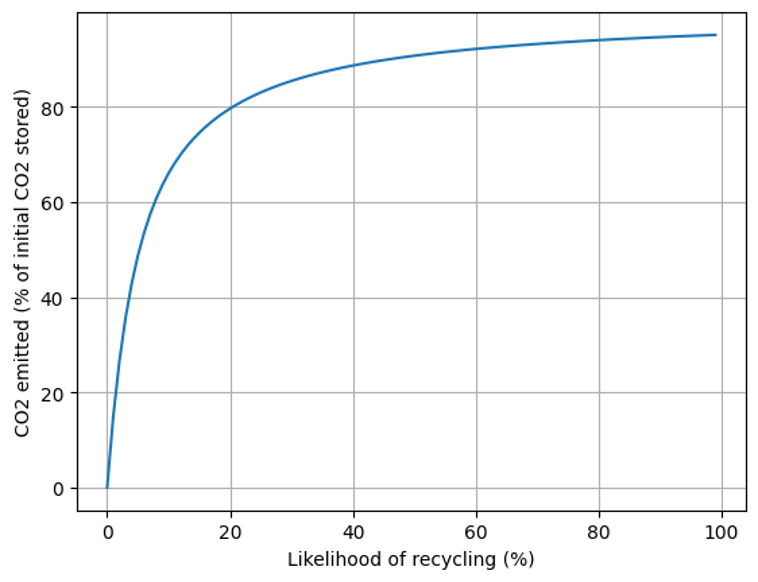
Figure A1.2. Sensitivity of the likelihood of closed-loop recycling on the amount of CO2 emitted to the atmosphere from closed-loop recycling over 1,000 years. The likelihood of closed-loop recycling was varied from 0 to 100%, while the likelihood of downcycling was decreased accordingly. All other parameters are kept constant at the values in Appendix 1, Table A1.1.
Sensitivity to Lifespan
Using the parameter values outlined in Table A1.1 but varying the lifespan for Option 1, a lifespan of 100 years results in a reversal risk of over 7%, whereas a lifespan of 10 years yields a reversal risk of around 5% (Figure A1.3). This is because more end-of-life transitions occur with the shorter lifespan, resulting in more of the concrete being landfilled, and landfills have a smaller annual loss to the atmosphere in Table A1.1 than in use cases.
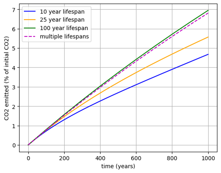
Figure A1.3. Sensitivity of the reversal risk to different lifespan assumptions over 1,000 years.
The effect of lifespan is highly dependent on the other parameters in Table A1.1. For example, if closed-loop recycling is set to a value greater than 0, then a short lifespan would result in a greater reversal than a long lifespan. This is because short lifespans will have more closed-loop recycling events which release CO2 to the atmosphere.
Project-Specific Reversal Risk Determination
Under this Module, Project Proponents may submit additional data to further constrain reversal risk. This may lead to a reduction in the total discount applied. The table below provides a summary of documentation that can be provided and how this may impact the reversal risk model. This list is not exhaustive, and additional documentation outside of what is listed can be provided.
Table A1.2. Recommendations for documentation submission and potential impact on uncertainty discounting.
| Parameter Name | Documentation | Rationale | Potential Impact on Uncertainty Discount | Notes |
|---|---|---|---|---|
| Regional Geology | Geologic maps of bedrock lithology | Assessment of acid generation potential in groundwater | Up to 3% reversal over 1,000 years | Can be sourced from regional geologic surveys. |
| Regional Hydrology | Groundwater pH data | Assessment of reversal risk from contact with acidic groundwater | Up to 3% reversal over 1,000 years | Data can be sourced from publicly available datasets or from direct measurement. |
| Regional Climatic Conditions | Average annual precipitation volume | Assessment of reversal risk from acid rain | Up to 3% reversal over 1,000 years | Data can be sourced from publicly available datasets. |
| Average annual precipitation pH | Assessment of reversal risk from acid rain | Up to 3% reversal over 1,000 years | Data can be sourced from publicly available datasets. | |
| Regional Operations | Transport radius | Determination of possible reversal risk within the transport radius, such as acidic groundwater | 3-5% reversal over 1,000 years | If unknown for a given Project, Project Proponents may use either the maximum possible transport distance or a conservative average distance. |
Footnotes
-
Global Cement and Concrete Association, Cement and Concrete Around the World ↩
-
Farfan, J., Fasihi, M. & Breyer, C. Trends in the global cement industry and opportunities for long-term sustainable CCU potential for Power-to-X. J. Clean. Prod. 217, 821–835 (2019). ↩
-
Moumin, Gkiokchan, et al. "CO2 emission reduction in the cement industry by using a solar calciner." Renewable energy 145 (2020): 1578-1596. ↩
-
Olivier, Jos GJ, Jeroen AHW Peters, and Greet Janssens-Maenhout. "Trends in global CO2 emissions. 2012 report." (2012). ↩
-
Goodbrake, Chris J., J. Francis Young, and Richard L. Berger. "Reaction of beta‐dicalcium silicate and tricalcium silicate with carbon dioxide and water vapor." Journal of the American Ceramic Society 62, no. 3‐4 (1979): 168-171. ↩
-
Monkman, Sean, Mark MacDonald, R. Doug Hooton, and Paul Sandberg. "Properties and durability of concrete produced using CO2 as an accelerating admixture." Cement and Concrete Composites 74 (2016): 218-224. ↩ ↩2 ↩3 ↩4
-
Zhang, Suhui, Qiang Yuan, Jun Ni, Caijun Shi, Keren Zheng, and Jingqiang Tan. "Study of CO2 Injection Timing within the Mixing Process of Ready-Mix Concrete for Win–Win Improvements of Mechanical Properties and CO2 Sequestration." ACS Sustainable Chemistry & Engineering 12, no. 4 (2024): 1480-1492. ↩
-
Monkman, Sean, and Mark MacDonald. "On carbon dioxide utilization as a means to improve the sustainability of ready-mixed concrete." Journal of Cleaner Production 167 (2017): 365-375. ↩
-
Luo, Shuang, Ming-Zhi Guo, and Tung-Chai Ling. "Modification of early-age microstructure and enhanced mechanical properties of cement paste via injecting low-dose CO2 at fresh stage." Construction and Building Materials 438 (2024): 137284. ↩
-
Liu, Zhuo, and Weina Meng. "Fundamental understanding of carbonation curing and durability of carbonation-cured cement-based composites: A review." Journal of CO2 Utilization 44 (2021): 101428. ↩
-
Rostami, Vahid, Yixin Shao, and Andrew J. Boyd. "Durability of concrete pipes subjected to combined steam and carbonation curing." Construction and Building Materials 25, no. 8 (2011): 3345-3355. ↩ ↩2
-
Zhang, Duo, and Yixin Shao. "Early age carbonation curing for precast reinforced concretes." Construction and Building Materials 113 (2016): 134-143. ↩
-
Ghouleh, Zaid, Roderick IL Guthrie, and Yixin Shao. "Production of carbonate aggregates using steel slag and carbon dioxide for carbon-negative concrete." Journal of CO2 Utilization 18 (2017): 125-138. ↩
-
O’Connor, J. (2004) Survey on actual service lives for North American buildings. Presented at Woodframe Housing Durability and Disaster Issues conference, Las Vegas, October 2004. ↩ ↩2 ↩3
-
RIBA, Lifespan, https://www.ribaj.com/culture/lifespan, Accessed 25/06/2024. ↩ ↩2
-
DEFRA, UK Statistics on Waste. ↩
-
Zhang, Duo, and Yixin Shao. "Effect of early carbonation curing on chloride penetration and weathering carbonation in concrete." Construction and Building Materials 123 (2016): 516-526. ↩ ↩2 ↩3
-
Lechat, Karl, et al. "Field evidence of CO2 sequestration by mineral carbonation in ultramafic milling wastes, Thetford Mines, Canada." International Journal of Greenhouse Gas Control 47 (2016): 110-121. ↩
-
Gras, A., et al. "Isotopic evidence of passive mineral carbonation in mine wastes from the Dumont Nickel Project (Abitibi, Quebec)." International Journal of Greenhouse Gas Control 60 (2017): 10-23. ↩
-
Plante, Benoît, et al. "Kinetic testing to evaluate the mineral carbonation and metal leaching potential of ultramafic tailings: Case study of the Dumont Nickel Project, Amos, Québec." Applied geochemistry 84 (2017): 262-276. ↩
-
Wilson, S. et al. Offsetting of CO2 emissions by air capture in mine tailings at the Mount Keith Nickel Mine, Western Australia: Rates, controls and prospects for carbon neutral mining. International Journal of Greenhouse Gas Control 25 (2014): 121-140. ↩
-
Rao, T. Rajeswara, and V. S. Chohan. "Kinetics of thermal decomposition of hydromagnesite." Chemical Engineering & Technology: Industrial Chemistry‐Plant Equipment‐Process Engineering‐Biotechnology 18.5 (1995): 359-363. ↩
-
Nordstorm, K., et al. “Hydrogeochemistry and microbiology of mine drainage: An update” Applied Geochemistry 57 (2015): 3-16. ↩
-
Vogler, N., Drabetzki, P., Lindemann, M., & Kühne, H. C. (2022). Description of the concrete carbonation process with adjusted depth-resolved thermogravimetric analysis. Journal of Thermal Analysis and Calorimetry, 147(11), 6167–6180. https://doi.org/10.1007/s10973-021-10966-1 ↩
-
Rao, T. Rajeswara, and V. S. Chohan. "Kinetics of thermal decomposition of hydromagnesite." Chemical Engineering & Technology: Industrial Chemistry‐Plant Equipment‐Process Engineering‐Biotechnology 18.5 (1995): 359-363. ↩
-
Zeebe, Richard E., and Dieter Wolf-Gladrow. CO2 in seawater: equilibrium, kinetics, isotopes. Vol. 65. Gulf Professional Publishing, 2001. ↩
-
V. Zivica, A. Bajza, Acidic attack of cement based materials – a review: part 1. Principle of acidic attack, Constr. Build. Mater., 15 (2001), pp. 331-340 ↩
-
V. Zivica, A. Bajza, Acidic attack of cement based materials – a review: part 2. Factors of rate of acidic attack and protective measures, Constr. Build. Mater., Volume 16, Issue 4, June 2002, Pages 215-222 ↩
-
V. Zivica, A. Bajza, Acidic attack of cement based materials – a review: part 3. research and test methods, Constr. Build. Volume 18, Issue 9, November 2004, Pages 683-688 ↩
-
Talati, S. et al. “Paving the way for low-carbon concrete”. White paper published Dec. 2020. ↩
-
“Cement and concrete companies leading the net-zero transition.” Cap 20 Report, July 11, 2024. ↩
-
Building fire reversals are based on US fire statistics. In 2021, there were 486,500 structure fires reported to fire departments in the US, and there were approximately 111 million buildings. ↩
Contributors