

Contents
1.0
Introduction
Hydrofluorocarbons (HFCs) and ozone-depleting substances (ODS), including chlorofluorocarbons (CFCs) and hydrochlorofluorocarbons (HCFCs), are classes of synthetic compounds used in refrigeration with high global warming potentials (GWPs) and atmospheric lifetimes ranging from months to centuries. While their persistence varies by compound, most are sufficiently long-lived to mix globally and contribute meaningfully to near-term climate forcing. Their controlled destruction therefore represents one of the most immediate and impactful opportunities to reduce radiative forcing and slow global temperature rise.
Significant CO2-equivalent warming potential already resides in deployed cooling equipment and end-of-life products around the world. In many regions, particularly Montreal Protocol Article 5 countries, the infrastructure needed to recover these gases at end of life is limited, recovery is not mandated or enforced, and the typical outcome is atmospheric release. The Kigali Amendment establishes a phasedown trajectory for HFC production and consumption, and the Montreal Protocol has driven substantial progress on ODS phase-out, but neither framework directly addresses the legacy bank of gases already in the field. The controlled destruction of these substances is complementary to both the ODS phase-out and the HFC phasedown. By preventing the venting of high-GWP compounds, such as during routine refrigerant servicing or at equipment end-of-life, projects implemented under this Protocol avoid contributing to warming while supporting compliance with international commitments.
This Protocol establishes the requirements and standards for quantifying, reporting, and verifying greenhouse gas emission reductions achieved through the collection and destruction of HFCs and ODS that would otherwise be released to the atmosphere. It provides a consistent framework for projects seeking to generate high-integrity credits for permanent mitigation of super-pollutant emissions, ensuring that credited reductions are real, additional, independently verified, and conservatively quantified. Emission reductions are credited exclusively on the basis of avoided GHG emissions (GWP-100); ozone co-benefits are not credited.
Beyond delivering verified climate outcomes, the Protocol contributes to the broader infrastructure, workforce capacity, and data that the refrigerant sector needs to manage end-of-life gases at scale. The collection networks, trained technicians, analytical testing capabilities, and reporting systems that destruction projects establish are the same capabilities that reclamation, equipment transition, and lifecycle management require. Every project generates publicly reported data on refrigerant type, quantity, source, chain of custody, and destruction performance, building an empirical base that does not exist today. Destruction is a necessary and permanent climate intervention and the operational foundation it creates enables the full suite of refrigerant management solutions to follow.
2.0
Sources, Reference Standards and Methodologies
Specific standards and Protocols that are utilized as the foundation of this Protocol, and for which this Protocol is intended to comply with, are the following:
- Isometric Standard
- ISO (International Organization for Standardization) 14064-2: 2019 – Greenhouse Gases – Part 2: Specification with guidance at The Project level for quantification, monitoring and reporting of greenhouse gas emission reductions or removal enhancements
Additional reference standards that inform the requirements and overall practices incorporated in this Protocol include:
- ISO 14064-3: 2019 - Greenhouse Gases - Part 3: Specification with Guidance for the verification and validation of greenhouse gas statements
- ISO 14040: 2006 - Environmental Management - Lifecycle Assessment - Principles & Framework
- ISO 14044: 2006 - Environmental Management - Lifecycle Assessment - Requirements & Guidelines
- AHRI 700 Standard
- UNEP TEAP Code of Good Housekeeping
Additional standards, methodologies and Protocols that were reviewed, referenced and informed the development of this Protocol include:
- VM0016 Destruction of Ozone-Depleting Substances and Hydrofluorocarbons, Version 2.0 (Verra, December 2025)
- GHR001 Methodology for Assessing Emissions Reductions via Collection and Destruction of HFCs, Version 1.1 (Global Heat Reduction Initiative, a program of Scientific Certification Systems Inc., December 2024)
- Draft Methodology for Recovery and Destruction of Hydrofluorocarbons in Article 5 Countries, Version 2.1 (Yale Carbon Containment Lab, 2024)
3.0
Applicability
Projects meeting the following applicability criteria are considered eligible for crediting under this Protocol:
- Eligible countries
- Refrigerants must be recovered from countries which have ratified the Kigali Amendment, and meet the country-level eligibility screen (see Section 6.3). Refrigerants recovered from Article 5 countries, meeting the rest of the applicability conditions are deemed additional. Non-Article 5 country projects require enhanced additionality demonstration.
- Other project activities (aggregation, destruction, laboratory analysis) may be implemented in separate countries from recovery.
- Eligible gases
- Projects must destroy eligible refrigerant gases:
- CFCs as specified in Montreal Protocol Annex A, Group I and Annex B, Group I
- HCFCs as specified in Montreal Protocol Annex C, Group I
- HFCs as specified in Montreal Protocol Annex F, Group I
- Eligible HFC refrigerant blends Additional refrigerant gases may be proposed for inclusion with approval by Isometric. Commercial blends containing any listed substance are also eligible.
- Projects must destroy eligible refrigerant gases:
- Eligible sources
- HFC or ODS must be recovered from sources that have a baseline scenario that includes total or partial atmospheric release. As such, only HFC and ODS refrigerants recovered from the following sources are eligible:
- Routine servicing
- End-of-life
- Recovered refrigerant must meet the following criteria:
-
To mitigate risk of virgin gas entering the recovery stream, any buy back payments rendered for recovered refrigerant must not exceed the price of virgin gas.
-
Be part of a product stewardship scheme or other program that creates incentives or mechanisms resulting in refrigerant destruction as an industry common practice.
Edge cases for the two above criteria, such as where a product stewardship program relies on revenue from carbon finance to fund destruction or where virgin gas prices fluctuate will be evaluated on a case-by-case basis.
-
- HFC or ODS must be recovered from sources that have a baseline scenario that includes total or partial atmospheric release. As such, only HFC and ODS refrigerants recovered from the following sources are eligible:
- Eligible destruction facilities
- Must be approved following the requirements and risk assessment in Section 8
The quantification, monitoring and documentation requirements in this Protocol support container-based handling of HFCs and ODS. Future versions may support alternative direct capture-to-destruction pathways such as via mobile destruction units, co-located recovery and destruction, or continuous-feed systems.
4.0
Relation to Isometric Standard
The following topics are covered briefly in this Protocol due to their inclusion in the Isometric Standard, which governs all Isometric Protocols. See in-text references to the Isometric Standard for further guidance.
4.1
Project Design Document
For each specific project to be evaluated under this Protocol, the Project Proponent must document project characteristics in a Project Design Document (PDD) as outlined in Section 3.2 of the Isometric Standard. The PDD will form the basis for project verification and evaluation in accordance with this Protocol, and must include consideration of processes unique to each project such as:
- documentation of official permitting
- detailed description of how recovered HFCs will be characterized
- description of the mitigation plan according to the environmental and social risk assessment in adherence with Section 5, including an accompanying robust monitoring plan to ensure efficacy
- description of the quantification strategy for gross CO2e reduction following Section 7
- description of all measurements and methods used to quantify processes relevant to the calculation of net CO2e reduction, cross-referenced with relevant standards where applicable
- description of all models used to quantify processes relevant to the calculation of net CO2e reduction that are not directly measurable
4.2
Validation and Verification
Projects must be validated and net CO2e reductions verified by an independent third party, consistent with the requirements described in this Protocol as well as in Section 4 of the Isometric Standard.
The VVB must adhere to these requisite components:
4.2.1
Verification Materiality
The threshold for Materiality, considering the totality of all omissions, errors and mis-statements, is 5%, in accordance with Section 4.3 of the Isometric Standard.
Verifiers should also verify the documentation of uncertainty of the GHG statement as required by Section 2.5.7 of the Isometric Standard.
Qualitative Materiality issues may also be identified and documented, such as:
- control issues that erode the verifier’s confidence in the reported data;
- poorly managed documented information;
- difficulty in locating requested information;
- noncompliance with regulations indirectly related to GHG emissions, removals or storage.
4.2.2
Site Visits
Project validation and verification must incorporate a site visit to project facilities in accordance with the requirements of ISO 14064-3, 6.1.4.2, including, at a minimum, a site visit at the destruction facility during the first Validation or Verification of a Project. Validators should, whenever possible, observe project operations to ensure full documentation of process inputs and outputs through visual observation (see Section 4 of the Isometric Standard).
4.2.3
Verifier Qualifications & Requirements
Verifiers and validators must comply with the requirements defined in Section 4 of the Isometric Standard. In addition, VVB teams must maintain and demonstrate expertise associated with the specific technologies of interest.
All VVBs are approved by Isometric independently and impartially based on alignment with Conflict of Interest policies, rotation of VVB policies, oversight on quality and the following requirements:
- VVBs must be able to demonstrate accreditation from:
- an International Accreditation Forum member against ISO 14065 or other relevant ISO standard, including but not limited to ISO 14034, ISO 17020, ISO 17029; or
- a relevant governmental or intergovernmental regulatory body.
- Alternatively, VVBs may be approved on a case-by-case basis if they are able to demonstrate to Isometric that they satisfy all required Verification needs and competencies required for the relevant Protocol and follow the guidelines of ISO 19011 or other relevant standards.
4.3
Ownership
Greenhouse gas reduction or avoidance can often be a result of a multi-step process, with activities in each step managed and operated by a different operator, company or owner. When there are multiple parties involved in the process, and to avoid double counting of net CO2e reductions, a single Project Proponent must be specified contractually as the sole owner of Credits. Contracts must comply with all requirements defined in Section 3.1 of the Isometric Standard.
4.4
Additionality
The Project Proponent must be able to demonstrate additionality through compliance with Section 3.5 of the Isometric Standard. Projects which meet the applicability conditions in Section 4 are deemed additional. The counterfactual scenarios and baselines are described in Section 6.3 of this Protocol.
Additionality determinations must be reviewed and completed at project validation, as well as in the event that significant changes to project operating conditions, such as the following:
- regulatory requirements or other legal obligations for project implementation change or new requirements are implemented;
- project financials indicate Carbon Finance is no longer required, potentially due to, for example:
- increased tipping fees for waste feedstocks;
- sale of co-products that make the business viable without Carbon Finance;
- reduced rates for capital access.
- Any review and change in the determination of additionality will not affect the availability of Carbon Finance and Credits for the current or past Crediting Periods, but, if the review indicates The Project has become non-additional, this will make The Project ineligible for future Credits.
4.5
Uncertainty
The uncertainty in the overall estimate of net CO2e impact as a result of The Project must be accounted for. The total net CO2e impact for a specific Reporting Period must be conservatively determined, and projects must conduct an uncertainty analysis for the net CO2e impact calculation in compliance with requirements outlined in Section 2.5.7 of the Isometric Standard.
4.5.1
Reporting of Uncertainty
Projects must report a list of all key variables used in the net CO2e removal calculation and their uncertainties, as well as a description of the uncertainty analysis approach, including:
- required measurements used for net CO2e calculation;
- emission factors utilized, as published in public and other databases used;
- values of measured parameters from process instrumentation, such as electricity usage from utility power meters;
- laboratory analyses.
The uncertainty information should at least include the minimum and maximum values of each variable that goes into the net CO2e calculation (see Section 7 for more details). More detailed uncertainty information should be provided if available, as outlined in Section 2.5.7 of the Isometric Standard.
In addition, a sensitivity analysis that demonstrates the impact of each input parameter’s uncertainty on the final CO2e uncertainty must be provided. Details of the sensitivity analysis method must be provided such that a third party can reproduce the results. Input variables may be omitted from an uncertainty analysis if they contribute to a < 1% change in the net CO2e reduction. For all other parameters, information about uncertainty must be specified.
4.6
Data Reporting and Availability
In accordance with the Isometric Standard, all evidence and data related to the underlying quantification of net CO2e reduction and environmental monitoring will be available to the public through Isometric’s Science Platform. That includes:
- Project Design Document
- GHG Statement
- Measurements taken
- Model specifications and output
- Emission factors used
- Scientific literature used
The Project Proponent can request certain information to be restricted (only available to authorized buyers, the Registry and VVB) where it is subject to confidentiality. However, that does not apply to any numerical data produced or used as part of the quantification of net CO2e impact.
In addition, in compliance with FAIR Principles, The Project Proponent should publicly disseminate deployment data that is relevant to scientific research, such as through open data repositories.
5.0
Environmental and Socio-Economic Safeguarding
5.1
Overarching Principles
Following the Isometric Standard, Credits issued under Isometric's HFC and ODS Recovery and Destruction Protocol are contingent on the implementation, transparent reporting and independent verification of comprehensive safeguards. Isometric takes a holistic approach to Environmental and Social Safeguarding (ESS) Risks associated with project activities must be weighed alongside risks of climate change to support responsible innovation.
Environmental and Social Safeguards must include, but are not limited to, the following Integrity Council for the Voluntary Carbon Market (ICVCM) Core Carbon Principles:
- Compliance: Project Proponents must comply with all national and local laws, regulations and policies.
- For HFC and ODS Recovery and Destruction projects, this may include obtaining the following permits:
- Host Country Destruction Permit
- Operational and Maintenance Permit
- Transboundary Movement Permit
- For HFC and ODS Recovery and Destruction projects, this may include obtaining the following permits:
- Risk Identification: Project Proponents must assess the potential environmental and social risks of project activities, in adherence with Section 3.10 of the Isometric Standard. Risk identification, impact assessment and mitigation plans must include, at a minimum, a discussion of pollution prevention and safe working conditions.
- Impact Assessment and Mitigation: Project Proponents must conduct an impact assessment and strategy for mitigation for each risk identified above. Impact assessments may be qualitative or quantitative.
- Monitoring and Adaptive Management: Implementation of risk mitigation measures must also be accompanied by a robust monitoring plan to ensure efficacy. Project Proponents must preemptively develop a remediation plan in the case that the identified risks occur and result in harm to the environment or society.
5.2
Alignment With Existing Safeguards
Project activities under this Protocol involve the handling, transport, storage, and destruction of hydrofluorocarbons (HFCs) and other controlled substances. These activities, if improperly managed, may pose risks to human health, worker safety, and the environment through fugitive emissions, generation of hazardous by-products, or inadequate operational controls. To mitigate these risks, the requirements in this Protocol are aligned with the requirements set forth in the UNEP Code of Good Housekeeping and UNEP Technology Screening Process.
The original text of these resources have been included in Appendix A (Code of Good Housekeeping) and Appendix B (Technology Screening Process) for reference. Where "ODS" or "ozone-depleting substance" appears in Appendix A or Appendix B, it must be interpreted as "ODS and HFC" or "controlled substance" as applicable to The Project activity.
6.0
System Boundary and Baseline
6.1
Reporting Period
The Reporting Period, , represents an interval of time over which reductions are calculated and reported for verification. The total net reduction is calculated using a series of measurements for a specified Reporting Period.
GHG emission calculations must include all emissions related to the project activities that occur within the Reporting Period. This includes:
- any emissions associated with project establishment allocated to the Reporting Period,
- any emissions that occur within the Reporting Period,
- any anticipated emissions that would occur after the Reporting Period that have been allocated to the Reporting Period, and
- leakage emissions that occur outside of the system boundary as a result of induced market changes that are associated with the Reporting Period.
For HFC and ODS destruction projects, a single Reporting Period must not exceed 1 year.
6.2
System Boundary & GHG Emissions Scope
The scope of this Protocol includes GHG sources, sinks and reservoirs (SSRs) associated with an HFC and ODS Destruction Project. A cradle-to-grave GHG Statement must be prepared encompassing the GHG emissions relating to the activities outlined within the system boundary. The system boundary must include all SSRs controlled by and related to The Project, including but not limited to the SSRs in Figure 1 and Table 1.
As noted in Section 6.3, the baseline scenario assumes atmospheric release (venting) of HFC and ODS refrigerants at equipment end-of-life or during servicing in the absence of any project activities.
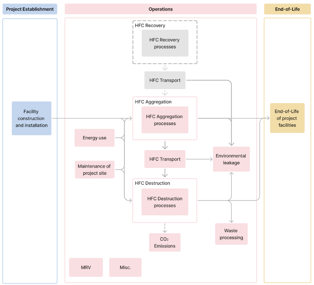
Figure 1. Process flow diagram showing system boundary for eligible HFC destruction projects.
The system boundary must include all GHG SSRs from activities related to the batch of Credits delivered within the Reporting Period that are associated with the establishment of The Project, operations and end-of-life activities that occur after the Reporting Period.
Any emissions from sub-processes or process changes that would not have taken place without the involvement of the reduction, such as subsequent transportation or substitute refrigerant production, must be fully considered in the system boundary. This allows for accurate consideration of additional, incremental emissions induced by the reduction process.
GHG SSRs within Table 1 deemed not appropriate to include in the system boundary may be excluded if robust justification and appropriate evidence is provided.
Table 1: Project System Boundary
Activity | GHG Source, Sink or Reservoir | GHGs | Scope | Timescale |
|---|---|---|---|---|
Project Establishment | Facility construction and installation | All GHGs | Equipment and materials manufacture, transport to site and construction site emissions. To include: • product manufacture emissions for equipment, buildings, infrastructure and temporary structures (lifecycle modules A1-A3). • Transport emissions associated with transporting materials and equipment to the project site(s) (lifecycle module A4). • Emissions related to construction and installation of the project site(s) (lifecycle module A5). | Before project operations start - must be accounted for in the first Reporting Period or amortized in line with allocation rules (see Section 7.3.1) |
Project Operations | HFC and ODS aggregation and storage | All GHGs | Emissions associated with aggregating and storing HFC and ODS refrigerants at aggregation facilities, including: • Energy use for facility operations • Maintenance, repair, replacement and refurbishment of storage equipment and facilities | Over each Reporting Period - must be accounted for in the relevant Reporting Period (See Section 7.3.2) |
HFC and ODS transportation | All GHGs | Emissions associated with transportation of HFC and ODS refrigerants between aggregation facilities and destruction facility, including: • Fuel use for transport vehicles • Maintenance, repair, replacement and refurbishment of transport equipment | ||
HFC and ODS destruction - direct emissions | CO2, HFCs | Direct emissions generated from thermal destruction, including: • CO2 emissions from oxidation of carbon content of destroyed HFCs and ODSs | ||
HFC and ODS destruction - process emissions | All GHGs | Emissions associated with the destruction process, including: • Fuel and energy use for thermal destruction • Maintenance, repair, replacement and refurbishment of destruction facility equipment • Waste processing | ||
Environmental leakage | All GHGs | Emissions associated with unintentional leakage of HFCs and ODSs during recovery, aggregation and storage, transportation, and / or destruction | ||
MRV | All GHGs | Any embodied, energy and transport emissions associated with sampling, monitoring, reporting and verification purposes. | ||
Misc. | All GHGs | Any SSRs not captured by categories above. | ||
Project End-of-life | End-of-life of project facilities | All GHGs | Anticipated end-of-life emissions (lifecycle Modules C1-4¹). To include deconstruction and disposal of the project site(s), equipment, vehicles, and infrastructure. | After Reporting Period - must be accounted for in the first Reporting Period or amortized in line with allocation rules (See Section 7.3.3) |
Miscellaneous GHG emissions are those that cannot be categorized by the GHG SSR categories provided in Table 1. The Project Proponent is responsible for identifying all sources of emissions directly or indirectly related to project activities and must report any outside of the SSR categories identified as miscellaneous emissions.
In some instances, the project activities may be integrated into existing activities, such as the recovery and subsequent transport of refrigerant gasses. Activities that were already occurring, and would continue to occur in the absence of The Project, may be omitted from the system boundary of the GHG accounting if evidence of this is provided.
The Project Proponent must consider all GHGs associated with SSRs, in alignment with the United States Environmental Protection Agency’s definition of GHGs, which includes: carbon dioxide (CO2), methane (CH4), nitrous oxide (N2O) and fluorinated gasses such as hydrofluorocarbons (HFCs), perfluorocarbons (PFCs), sulfur hexafluoride (SF6) and nitrogen trifluoride (NF3).
All GHGs must be quantified and converted to CO2e. GHGs must be converted to CO2e in the GHG Statement using the 100-yr Global Warming Potential (GWP) for the GHG of interest, based on the most recent volume of the IPCC Assessment Report (currently the Sixth Assessment Report).
Emissions associated with a project's impact on activities that fall outside of the system boundary of a project must also be considered. This is covered under Safeguards Against Leakage in Section 6.4.
6.3
Baseline Scenario
This section establishes the baseline scenario against which emission reductions are quantified and the additionality framework that determines whether credited destruction would have occurred without Carbon Finance. Projects meeting the eligibility criteria in applicability are deemed additional.
6.3.1
Baseline Fates of Eligible Refrigerants
In the absence of project activities, the general fate of HFC and ODS refrigerants at end of life or during servicing may include any combination of the following outcomes:
- Imminent atmospheric release (venting). Refrigerant is released to the atmosphere during servicing, equipment decommissioning, or disposal. This is the predominant fate in Article 5 countries lacking recovery mandates or infrastructure.
- Recovery for reuse or reclamation. Refrigerant is recovered and returned to the commercial refrigerant market, either as-is or after processing to virgin-equivalent specifications. The gas may face eventual release through operational leakage over the remaining equipment lifetime.
- Destruction without Carbon Finance. Refrigerant is destroyed at a permitted facility outside of any GHG crediting programme, whether voluntarily, as part of a product stewardship scheme, or under a government mandate. This may also include cases where products are disposed of at an incineration facility where destruction occurs as a by-product of general waste management.
- Continued storage in equipment or stockpiles. Refrigerant remains partially or entirely installed in operating equipment, or is held in stockpiles. The timing and extent of eventual release is uncertain.
The fate of the refrigerants from eligible sources could be a mix of outcome 1-3.
The following baseline outcomes are not eligible for crediting, and are excluded based on source eligibility:
- Refrigerant that would have been destroyed in the absence of The Project (outcome 3). Including this material in the creditable baseline would overstate reductions.
- Refrigerant that would remain in operating equipment or in sealed stockpiles (outcome 4). The timing and magnitude of eventual release from these sources is speculative, and crediting speculative future emissions would undermine conservative quantification.
6.3.2
Counterfactual for Recovered Refrigerant
Isometric will maintain an annually updated set of country-level default values which describe the relative proportion of refrigerant venting, reuse and destruction in the baseline. These default rates exclude other projects implemented under GHG programs. When the cumulative reuse and destruction rate falls below 50% (or 0.50), the country shall no longer be eligible for further credit. For predictability, a project’s default values will be fixed for 5 years. After 5 years, the default values will be updated according to the current year’s default values.
In 2026, for projects in eligible Article 5 countries, the following default assumptions in Table 2 apply.
Table 2: Default rates of venting, reuse and destruction in Article 5 countries.
Parameter | HFC | CFC | HCFC |
|---|---|---|---|
1 | 1 | 1 | |
0 | 0 | 0 | |
0 | 0 | 0 | |
Leakage emissions (Section 7.3.4) | Yes | No | No |
HFC
Venting of HFC refrigerants at end of life and during servicing is near-universal in Article 5 countries, where recovery infrastructure is limited and there is typically no economic incentive or regulatory requirement for recovery. However, some informal recovery-for-reuse does occur (e.g., technicians recovering refrigerant during servicing for recharging the same or other equipment), and a blanket assumption of zero reuse would overstate the baseline. The following default rates incorporate a conservative 2% reuse fraction to account for this residual activity.
CFC
CFC production has been fully phased out in all countries under the Montreal Protocol (Article 5 deadline: 2010). No new CFC is being manufactured. However, significant quantities of CFC remain in legacy equipment (older commercial and industrial refrigeration, centrifugal chillers) and in stockpiles, particularly in Article 5 countries. Recovered CFC has limited but nonzero residual value for topping up legacy equipment that cannot be economically retrofitted.
HCFC
HCFC production is being phased out under the Montreal Protocol but remains ongoing at reduced levels in Article 5 countries (97.5% reduction from baseline required by 2025, complete phase-out by 2030 for Group 1; 2040 for Group 2). HCFC-22 remains the dominant working refrigerant in much of the Article 5 installed base, particularly in residential and light commercial air conditioning. Recovered HCFC-22 has meaningful commercial value because the installed equipment base is large and retrofit costs are high, creating demand for recovered gas to service existing systems.
Compliance rate adjustments
Where recovery or destruction of refrigerants is mandated by national law implementing the obligations to Kigali Amendment phasedown or Montreal Protocol (e.g., national HFC management regulations, mandatory recovery-at-servicing rules, or end-of-life destruction requirements), and this mandate is demonstrably enforced, the baseline must be adjusted to reflect gradually increasing compliance. Venting bans alone do not trigger this adjustment; the mandate must require destruction action. Compliance rate adjustments will be triggered only where a host country has enacted and demonstrably enforces a requirement to destroy or reuse refrigerants at end of life. Enforcement is evaluated through published compliance data, government enforcement reports, or equivalent evidence. As of 2026, no Article 5 country is known to enforce such a requirement for HFCs, CFCs, or HCFCs.
6.3.3
Climate Impact of Baseline Venting, Reuse and Destruction
The release efficiency of refrigerant gases that are vented, reused and destroyed are indicated in Table 3. These values are used for net reduction quantification as described in Section 7.
Table 3: Default release efficiency factors for venting, reuse and destruction.
Parameter | Symbol | Default Value |
|---|---|---|
Release efficiency of refrigerant vented to atmosphere | 1 | |
Release efficiency of refrigerant reused | 0 | |
Release efficiency of refrigerant destroyed | 0 |
The release efficiency of reused refrigerant is currently set to zero, reflecting the Protocol's design choice to credit only the avoided emissions from the fraction that would have been imminently vented. Gas that would have been reused faces eventual atmospheric release through operational leakage, but the timing and magnitude are uncertain and vary by equipment type, maintenance practice, and remaining useful life. Setting avoids speculative crediting of delayed emissions and prevents potential double counting. This value may be revised in future Protocol versions as lifecycle refrigerant management (LRM) practices in Article 5 countries evolve and empirical data on in-service leak rates becomes available from deployed projects.
6.4
Safeguards Against Market Leakage
In the context of HFC destruction, secondary effects refer to market effects (i.e., market leakage) caused when The Project diverts HFC refrigerant from reclamation or reuse into destruction. For HFCs (Annex F, Group I), the Kigali Amendment requires a phasedown, not a phase-out, of production and consumption. Non-Article 5 countries must reach 85% reduction by 2036, while Article 5 countries phase down to 15–20% of baseline by the mid-2040s. Because ongoing production is legally permitted within phasedown limits, the interaction between destruction crediting and consumption accounting requires active monitoring. Additionally, because HFCs continue to be produced and consumed as working refrigerants, destruction of HFCs may create demand for substitute chemicals.
ODS market leakage is set to zero because ODS production is in terminal decline under the Montreal Protocol's phase-out schedule, and destruction cannot be offset by producing more of the same substance.
The Project activity must not create an economic incentive for the production or import of new HFCs for the purpose of destruction. The following conditions must be satisfied:
-
Country-level applicability to safeguard against increased production or import: Under the Montreal Protocol’s consumption formula (Consumption = CS_Produced − CS_Destroyed − CS_Feedstock + Imports − Exports), destroyed refrigerant is subtracted from both baseline and stepdown consumption values. This creates a theoretical mechanism by which credited destruction could lower a country’s calculated consumption, potentially creating headroom for additional production or imports above what the phasedown schedule would otherwise allow. Historical evidence indicates that this risk is low. Analysis of Ozone Secretariat data from 1986–2022 across all Article 5 parties and all controlled substances identified only one instance in which a small quantity of destruction was used as the basis for phasedown compliance, representing approximately 0.1% of that country’s total production in that year. Nevertheless, this Protocol implements scenario-differentiated country-level eligibility criteria.
Country eligibility for HFC destruction crediting is determined by the following scenario framework (Table 4), which differentiates treatment based on Kigali Amendment ratification status, whether the national HFC baseline has been established, and whether the country is an HFC producer.
Table 4: Country eligibility scenario framework
Scenario | Kigali Ratified | Baseline Set | Producer | Result | Applies To | Key Considerations |
|---|---|---|---|---|---|---|
I | No | — | — | Exclude | Any A5 country yet to ratify the Kigali Amendment | Kigali ratification is a prerequisite for eligibility. No exceptions. |
II | Yes | No | — | Include | A5 Group 2 countries with Kigali ratified (e.g., India). Baseline years: 2024–2026. | Destruction during baseline-setting years reduces the baseline consumption calculation and all subsequent stepdown targets. Early action is especially effective and should be promoted. No production/import check is required at this stage because phasedown limits have not yet been set. Confirm that the baseline-setting period has not yet concluded for the source country. If the baseline has been set since the previous verification, reclassify to Scenario III or IV as applicable. |
III | Yes | Yes | No | Include, with check | A5 Group 1 non-producer countries with baseline set (e.g., Indonesia). | Destruction must not enable consumption above stepdown limits. Country is eligible if: Consumption Limit ≥ Imports − Exports − CSFeedstock. If the check fails, credits are discounted or the country is removed from eligibility. |
IV | Yes | Yes | Yes | Include, with check | A5 Group 1 producer countries with baseline set (e.g., China). | Highest-scrutiny scenario. Country is eligible if: Consumption Limit ≥ CSProd + Imports − Exports − CSFeedstock. Must confirm destruction has not enabled production or imports above phasedown limits. Discount or removal applies if the check fails. |
V | Yes | Yes | — | Project method | Non-Article 5 countries (all developed countries). | HFC phasedown already underway (first stepdown 2019/2020). ODS production fully phased out. Regulatory surplus must be demonstrated against existing mandates (e.g., EU F-gas Regulation, US AIM Act). Additionality requires project-method demonstration (barrier/investment analysis). |
Transparency in voluntary carbon market (VCM) reporting provides a complementary safeguard. Destruction quantities credited under this Protocol will be publicly reported and can be cross-referenced against national reports to the Ozone Secretariat, enabling independent verification that credited destruction is not being used to inflate allowable consumption. This transparency layer is expected to be a deterrent against manipulation.
- Economic screen against manufacture-for-destruction: To ensure there is no net economic incentive to manufacture or procure new HFCs for destruction, Project Proponents must demonstrate that total payments made to HFC supplies, aggregators, or intermediaries do not exceed the prevailing market cost of equivalent virgin refrigerant in the relevant jurisdiction.
The Project Proponent must consider leakage emissions when HFC destruction could displace reuse, when the reuse rate is greater than 5% (0.05). The quantification approach considers (detailed in Section 7.3.4:
- Production of substituted refrigerants: upstream emissions associated with the manufacture of the replacement refrigerant; and
- Atmospheric release during use: the substitute refrigerant, once charged into equipment, gradually leaks to the atmosphere during normal operation over the 10-year crediting period. The leakage calculation captures the difference in cumulative leak rates between the destroyed HFC (had it been reclaimed and re-used) and the substitute chemical, ensuring that projects are not credited for any GWP reduction from switching to a lower-GWP substitute.
7.0
Quantification of Net Emissions Impact
7.1
Net Reduction Calculation
The net CO2e reduction equation is:
Equation 1
Where:
- represents the net CO2e reduction for the Reporting Period, RP, in tonnes of CO2e.
- represents the HFC emissions which would have occurred in the absence of The Project, over the Reporting Period, RP, in tonnes of CO2e.
- represents the CO2e emissions from the associated LCA in The Project over the Reporting Period, RP, in tonnes of CO2e.
7.2
Calculation of CO2eBaseline
The Project Proponent must determine the baseline scenario for all emissions using the following set of equations. Total baseline emissions are the sum of baseline emissions from each substance class present in the destroyed material:
Equation 2
Where:
- represents total baseline emissions from all eligible refrigerants over the Reporting Period, RP, in tonnes CO2e.
- represents baseline emissions attributable to HFC constituents, in tonnes CO2e.
- represents baseline emissions attributable to CFC constituents, in tonnes CO2e.
- represents baseline emissions attributable to HCFC constituents, in tonnes CO2e.
7.2.1
Baseline Emissions From a Substance Class
Each substance-class baseline equation follows the same general structure but uses substance-class-specific default rates. The HFC baseline equation is presented in full below. The CFC and HCFC baseline equations follow the same structure, substituting the relevant substance-class-specific default values and GWP values.
Baseline emissions from HFC refrigerants are determined based on the counterfactual fate of HFCs in the absence of The Project activity, accounting for the proportion of HFCs that would be vented, reused, or destroyed under business-as-usual conditions.
Equation 2
Where:
- represents baseline emissions from HFC refrigerants which would be released into the atmosphere in the absence of The Project activity, over the Reporting Period, RP, in tonnes CO2e.
- Isometric default values (see Section 6.3.2):
- represents the mass fraction of HFCs which would be vented into the atmosphere in the baseline, unitless.
- represents the release efficiency factor for refrigerant gases which would be vented, unitless.
- represents the mass fraction of HFCs which would be reused in the baseline, unitless.
- represents the release efficiency factor for refrigerant gases which would be reused, unitless.
- represents the mass fraction of HFCs which would be destroyed in the baseline, unitless.
- represents the release efficiency factor for refrigerant gases which would be destroyed, unitless.
- Project-specific values:
- represents the eligible mass of HFC constituents in container sent for destruction by The Project activity, in tonnes. For containers holding only HFCs, (the total eligible mass per Equation 4). For containers holding a mixture of HFCs, CFCs, and/or HCFCs, is the HFC mass fraction of the eligible mass. See Equation 5.
- represents the effective mass-weighted 100-year GWP of the HFC constituents in container , in tCO2e/t HFC. See Equation 3.
- represents the total number of containers sent for destruction over the Reporting Period, RP.
7.2.1.1
Effective GWP
For containers with multiple HFC species, the effective GWP of the HFC fraction is:
Equation 3
Where:
- represents the 100-year GWP of HFC species per the IPCC AR6 values, in tCO2e/t HFCj. Ineligible constituent gases have .
- represents the mass fraction of HFC species within the HFC fraction of container , unitless. Determined from laboratory analysis (Section 8.2.4). Note: is normalized to the HFC fraction only, such that across all HFC species in the container.
- represents the total number of distinct HFC species within container .
7.2.1.2
Eligible Mass
Moisture and high boiling residue are non-refrigerant contaminants that accumulate during recovery, storage, and handling. Moisture is typically present as dissolved or free water; high boiling residue includes compressor oils, sealants, and other non-volatile contaminants. Both must be deducted from the gross mass to determine the quantity of refrigerant eligible for crediting.
The eligible mass in a container is calculated as:
Equation 4
Where:
- represents the full container weight of container measured up to 2 days prior the destruction event, in tonnes. Determined by direct measurement, see Section 8.1.5.
- represents the full empty weight of container measured up to 2 days after the destruction event, in tonnes. Determined by direct measurement, see Section 8.1.5.
- represents the moisture, in ppm by mass. Determined from sample analysis, see Section 8.2.4.
- represents the fraction of high boiling reside, in %. Determined from sample analysis, see Section 8.2.4.
Where a container holds a mixture of substances from more than one class (e.g., both HFCs and HCFCs), the total eligible mass (per Equation 4) must be allocated to each substance class based on the composition analysis results.
The eligible mass attributable to substance class in container is:
Equation 5
Where:
- represents the total eligible mass of container per Equation 4, in tonnes.
- represents the mass fraction of substance class (HFC, CFC, or HCFC) in container , determined from laboratory composition analysis.
7.2.2
Constraint Equations
The following constraints must be satisfied.
Container-level composition constraint
The sum of the mass fractions of all constituent species in a container must equal 1. This constraint operates at the container level, not the substance-class level:
Equation 6
Where:
- represents the mass fraction of constituent species (across all substance classes) in container .
- is the total number of distinct species in the container.
This is the primary constraint verified against the laboratory composition analysis.
Substance-class allocation constraint
The mass fractions allocated to each substance class must sum to 1 (excluding non-eligible constituents already removed via Equation 6):
Equation 7
Where:
- is the mass fraction of non-eligible constituents (e.g., hydrocarbons, nitrogen, air).
Non-eligible constituents receive in the baseline calculation.
Baseline fate constraint
For each substance class , the sum of the mass fractions for baseline fates must equal 1:
Equation 8
7.2.3
Adjustments for Provenance Gaps
An adjustment is applied when the VVB determines that one or more field containers aggregated into a destruction container lack adequate provenance documentation, such that the verifier cannot confirm with reasonable assurance that the material was recovered from an eligible source in an eligible jurisdiction. Examples include, but are not limited to:
- Missing or incomplete collection log for the field container.
- Missing or inconsistent attestation from the point of origin.
- Significant weight discrepancies between the collection log and the aggregation intake log that cannot be reconciled.
- Inability to confirm the country of origin for the field container.
Adjustment
- Where provenance documentation for a field container is insufficient, the mass of that field container must be excluded from the eligible mass of the aggregated container. The excluded mass is the mass recorded at the aggregation intake log for that field container (Section 8.1.3).
- Where the aggregated container holds a mixture of substances (i.e., field containers containing different refrigerant types were consolidated together), and the specific composition of the excluded field container is unknown, the excluded mass must be conservatively assumed to consist entirely of the highest-GWP species identified in the aggregated container's composition analysis. This ensures that the GWP impact of the provenance gap is not understated.
- Where the excluded field container mass accounts for more than 50% of the total aggregated container mass, the entire container is ineligible for crediting. This threshold reflects the point at which the provenance gap is sufficiently large that the remaining material cannot be considered reliably characterized.
7.3
Calculation of CO2eProject
is the total GHG emissions associated with a Reporting Period, RP. This can be calculated as:
Equation 9
Where:
- represents the total GHG emissions for a Reporting Period, RP, in tonnes of CO2e.
- represents the GHG emissions associated with project establishment, represented for the Reporting Period, RP, in tonnes of CO2e, see Section 7.3.1.
- represents the total GHG emissions associated with operational processes for a Reporting Period, RP, in tonnes of CO2e, see Section 7.3.2.
- represents GHG emissions that occur after the Reporting Period and are allocated to a Reporting Period, RP, in tonnes of CO2e, see Section 7.3.3.
- represents GHG emissions associated with secondary effects (substitute refrigerant production and use), over a given Reporting Period, in tonnes of CO2e, see Section 7.3.4.
7.3.1
Calculation of CO2eEstablishment,RP
GHG emissions associated with project establishment should include all historic emissions incurred as a result of project establishment, including but not limited to the SSRs set out in Table 1. This includes the following emissions sources:
- Equipment and materials manufacture
- Equipment and materials transport to site
- Construction and installation of aggregation facilities
- Other miscellaneous emissions not captured by the above categories
For HFC destruction projects, project establishment emissions must be quantified for aggregation or destruction facilities that meet either of the following criteria:
- Greenfield facility: a facility that was purpose-built for The Project activity and was not operational prior to The Project start date.
- Major refurbishment: an existing facility that has undergone significant physical modification involving the replacement, addition, or structural alteration of core processing equipment.
Project establishment emissions occur from the point of project inception up until the first Reporting Period. Establishment emissions may be accounted for in the following ways, with the allocation method selected and justified by The Project Proponent:
- as a one-time deduction from the first verification, or
- amortized over the first crediting period (or less) as annual emissions.
7.3.2
Calculation of CO2eOperations,RP
GHG emissions associated with must include all emissions associated with operational activities, including but not limited to the SSRs set out in Table 1.
emissions occur over the Reporting Period for the deployment being credited and are applicable to the current deployment only. emissions must be attributed to the Reporting Period in which they occur.
7.3.2.1
Direct Emissions From Destruction
It is assumed that sufficient oxygen exists within the destruction process to completely convert all carbon from HFCs and ODS into CO2. The direct CO2 emissions are calculated as:
Equation 10
Where:
- represents the direct emissions from HFC destruction over the Reporting Period, RP, in tonnes CO2e.
- represents the total number of containers sent for destruction by The Project activity, over the Reporting Period, RP.
- represents the effective carbon content of container in tonnes CO2 per tonne refrigerant.
For mixed gas containers:
Equation 11
Where:
- represents the mass fraction of the constituent refrigerant in container , unitless. Determined from lab analysis, see Section 8.2.4.
- represents the carbon content of refrigerant , in tonnes CO2 per tonne HFCj.
- represents the total number of constituent refrigerants within a single container.
7.3.3
Calculation of CO2eEnd-of-Life,RP
CO2eEnd-of-Life,RP includes all emissions associated with activities that are anticipated to occur after the Reporting Period, but are directly or indirectly related to the Reporting Period. For example, this could include end-of-life emissions for project equipment (indirectly related to all deployments).
GHG emissions associated with CO2eEnd-of-Life,RP may occur from the end of the Reporting Period onwards, and typically through to completion of project site deconstruction and any other end-of-life activities.
GHG emissions associated with activities that are indirectly related to all deployments may be allocated in the same ways as set out in CO2eEstablishment,RP.
End-of-life emissions must be quantified for any facility for which establishment emissions are required under the criteria set in Section 7.3.1.
7.3.4
Calculation of CO2eLeakage,RP
CO2eLeakage,RP includes emissions associated with secondary effects from The Project activity.
Projects must calculate CO2eLeakage,RP where the baseline reuse fraction is greater than 0.05 (5%). Where the baseline venting rate is 100%, leakage is assumed to be zero.
CO2eLeakage,RP is calculated as follows:
**Equation 12 **
Where:
- represents total emissions from secondary effects (leakage) by The Project activity over the Reporting Period, RP, in tonnes CO2e.
- represents the mass fraction of refrigerant which would be reused or remain in storage in the baseline, unitless.
- represents emission factor associated with production of substitute refrigerant, in t CO2e/ t refrigerant.
- represents the global warming potential of destroyed refrigerant i, in tCO2e/t refrigeranti.
- represents the global warming potential of substitute refrigerant for refrigerant i, in tCO2e/t Substitute.
- represents the total leak rate over a 10-year period.
- represents the total number of containers sent for destruction by The Project activity, over the Reporting Period, RP.
The total leak rate over a 10-year period,
is calculated as:
Equation 13
Where:
- represents the annual rate that refrigerants leak out of equipment into the atmosphere.
- represents the crediting period in years. By default, = 10.
Assumptions on substitute refrigerant are as follows:
- If official published data, research, or industry studies are not available, the default substitute gas is assumed to be HFC-134a (GWP = 1,530).
- The default emissions factor for HFC-134a production must be sourced from reputable sources, such as officially published data, recognized LCA databases, or verifiable industry studies.
- The GWP of the substitute gas is always assumed to be greater than or equal to the GWP of the destroyed gas. Project Proponents shall not be credited for decreased leakage due to a lower GWP substitute gas.
Assumptions on the physical leak rate of refrigerants are as follows:
- The default physical annual leak rate is 0.137 (13.7%), if official published data, research or industry studies specific to the equipment are not available.
7.4
Emissions Accounting Requirements
7.4.1
Data Collection
Project Proponents must use the most representative, accurate, and plausible data that is available at the time of assessment in the GHG Statement. Activity data used to inform GHG accounting may be primary data or secondary data. Project Proponents must strive to use primary data in GHG accounting, but secondary data may be used where primary data is either not available or not practical. More details on data requirements, including data quality hierarchy and data quality principles, can be found in Section 3 of the GHG Accounting Module v1.0.
Where primary data is available, the following activity data hierarchy applies to the quantification of project operations emissions from refrigerant aggregation, transport and destruction activities. Where primary data for a specific emission source component is not available or not practical to obtain, Project Proponents shall follow the data quality hierarchy in Section 3 of the GHG Accounting Module v1.1.
Tier 1 - Primary data
The Project Proponent must directly measure or record project-specific activity data for each emission source component (aggregation facility energy, transport, destruction facility energy). This includes metered electricity consumption, fuel purchase records, recorded transport distances by vehicle type, and mass of refrigerant per shipment.
Tier 1 is the default requirement. All projects must apply Tier 1 for all emission source components during the first 3 complete Reporting Periods following project registration.
Tier 2 - Project-Specific benchmarks
After accumulating at least three complete Reporting Periods of primary data for a given emission source component, The Project Proponent may derive a project-specific activity data intensity benchmark for that component (e.g., MWh per tonne HFC destroyed, km per tonne HFC transported). Benchmarks must be derived on a per-component basis; The Project Proponent may apply different tiers to different components provided eligibility criteria are independently met.
Each benchmark must be calculated as the throughput-weighted average of the per-tonne activity data intensity across the qualifying Tier 1 periods, where the weighting reflects the mass of refrigerant processed or destroyed in each period. When applied, the activity data input for the relevant component is the product of the benchmark intensity and the quantity of refrigerant processed or destroyed in the current period; current-period emission factors are then applied.
Benchmarks shall be recalculated at least once per crediting period. If a material change occurs in operations affecting a benchmarked component, including a change in destruction technology, destruction facility, primary transport mode, or geographic distribution of recovery sites, The Project Proponent must revert to Tier 1 for the affected component(s). A new benchmark may only be derived after three complete Reporting Periods of Tier 1 data following the change.
7.4.2
Materiality
Project Proponents may exclude any SSRs included in Table 1 from the final net reduction quantification if these are demonstrated to be negligible. Negligible SSRs are those which fall below a Materiality threshold based on environmental significance of less than 1% of net CO2e reduction in any given Reporting Period. The sum of negligible SSRs must not be equal or more than 1% of net reduction.
To demonstrate this, Project Proponents may utilize an economic input-output (EEIO) approach as a preliminary screening test, estimating emissions based on project financial data (e.g., CAPEX data) combined with EEIO emission factors. If this screening demonstrates that emissions are below the Materiality threshold, emissions can be excluded, or can be estimated using high level estimations if included. See Section 5 of the Isometric GHG Accounting Module v1.0 for more details on the approach and example libraries.
Alternatively, where financial data is unavailable, Project Proponents may use other benchmarks to estimate emissions. For example, when quantifying the embodied emissions of existing infrastructure, proponents may rely on physical benchmarks from industry-standard life cycle inventory databases based on physical parameters, such as facility area (e.g., kgCO2e/m2) or processing capacity (e.g., tCO2e/tonne of throughput).
7.4.3
Ancillary Activities
Ancillary activities, such as supplementary research and development activities and corporate administrative activities, that are associated with a project but are not directly or indirectly related to the issuance of Credits can be excluded from the system boundary.
7.4.4
Energy Use Accounting
This section sets out specific requirements relating to quantification of energy use as part of the GHG Statement. Emissions associated with energy usage result from the consumption of electricity or fuel.
Electricity
Examples of electricity usage may include, but are not limited to:
- Operation of equipment at aggregation facilities
- Refrigeration and cooling systems for storage
- Facility and building operation (lighting, HVAC, control rooms, safety and monitoring systems)
- Electricity consumption at destruction facilities (for plasma arc or other destruction technologies)
The following calculation approach must be used to estimate emissions from project’s electricity consumption:
Equation 14
Where:
- represents total emissions from The Project’s electricity consumption over the Reporting Period, RP, in tonnes CO2e
- represents the total electricity consumed from the grid over the Reporting Period, RP, in kWh
- represents the emission intensity of the electricity grid over the Reporting Period, RP, in kgCO2e/kWh
- represents the transmissions and distribution grid losses factor which is set at 25% for all projects.
- represents the total electricity consumed from a non-grid generator over the Reporting Period, RP, in kWh
- represents the emission factor associated with the non-grid generator, in kgCO2e/kWh
Project may determine the emission intensity of the electricity grid, , using the following hierarchy:
- Projects may use Combined Margin (CM) emission factors from a reputable source. The suitability and technical rigor of the selected CM factor and its source will be evaluated by Isometric on a case-by-case basis during project validation.
- If appropriate CM factors are not available for the location of The Project, Project Proponent must apply one of the following default values for , based on the share of renewable and nuclear energy in the electric grid:
- 1.3 kgCO2e/kWh if the share of renewables and nuclear is less or equal 33%;
- 0.87 kgCO2e/kWh if the share of renewables and nuclear is between 33% and 67%;
- 0.44 kgCO2e/kWh if the share of renewables and nuclear exceeds 67%.
If the generation source is a captive fossil fuel fired power plant, Projects should make every attempt to gather information on the emission intensity of the technology generating the electricity. Where a specific emission intensity is not available, Projects must apply a default of 1.3 kgCO2e/kWh.
Fuels
Examples of fuel usage may include, but are not limited to:
- Fossil fuels utilized for space heating, boiler operation, or backup power generation at aggregation facilities.
- Fuel consumed (e.g., LPG or diesel) by on-site material handling equipment, such as forklifts, used to move cylinders within aggregation or destruction facilities.
- Combustion fuels (e.g., natural gas or fuel oil) required to fire the incinerator, maintain reaction chamber temperatures, or operate afterburners at the thermal destruction facility.
Section 6 of the Energy Use Accounting Module v1.3 provides requirements on how fuel-related emissions must be calculated in a Project.
7.4.5
Transportation Emissions Accounting
This section sets out specific requirements relating to quantification of transportation emissions as part of the GHG Statement.
Emissions associated with transportation include transportation of products and equipment as part of a Reporting Period's activities. Examples may include, but are not limited to:
- Transportation of HFCs and ODS from aggregation facilities to destruction facilities
Section 4.2 of the GHG Accounting Module v1.0 provides requirements on how transportation-related emissions must be calculated in a Project.
7.4.6
Embodied Emissions Accounting
This section sets out specific requirements relating to quantification of embodied emissions as part of the GHG Statement. Embodied emissions are those related to energy use or other emissions during the manufacture of equipment and materials used in a process.
Examples of project-specific materials and equipment that must be considered as part of the embodied emission calculation include but are not limited to:
- Storage containers and cylinders
- Aggregation facility equipment
- Any materials used for repair, maintenance, or retrofits
The GHG Accounting Module v1.0 sets out the approach to be followed to account for embodied emissions, including life cycle stages to be considered (Section 4.1), and data sources and emission factors (Section 3.4).
8.0
Monitoring and Documentation Requirements
This section establishes monitoring and documentation requirements necessary to ensure the accuracy, completeness, and credibility of HFC and ODS destruction projects.
Requirements are grouped based on asset type. HFC and ODS destruction projects use the following assets:
- Recovered Containers
- Samples
- Destruction Facility
Requirements are further organized into two categories:
- Validation requirements include evidence and documentation required at initial project registration.
- Verification requirements include ongoing evidence to be submitted for each Reporting Period.
Requirements are grounded in the following principles:
- Technical Capability: To minimize risk associated with safe handling of HFCs and ODS and ensure that destruction will be performed in a manner consistent with protecting the environment.
- Measurement Accuracy: HFC and ODS quantities must be measured with sufficient precision to support credible emission reduction claims. Given the high GWP of HFCs—ranging from 164 to 14,600 times that of CO2—even small measurement errors can translate to significant over- or under-crediting. Requirements for calibrated scales, accredited laboratories, and standardized sampling procedures ensure measurement uncertainty remains within acceptable bounds.
- Chain of Custody Integrity: HFCs and ODS must be tracked from point of collection to destruction to prevent double-counting, fraud, and leakage. Documentation requirements establish an auditable trail that verifiers can use to confirm that credited material was actually collected from eligible sources and destroyed at approved facilities.
8.1
Recovered Container
The following requirements must be met for each recovered container.
8.1.1
Container
Validation requirements
- Each container must be assigned a unique ID. Containers must be labelled with the container ID.
- The Project Proponent must maintain an unbroken chain of custody for each container from the point of origin to the point of destruction
- Containers must provide functional containment sufficient to prevent loss of refrigerant under normal storage and transport conditions. Containers must show no active leakage or visible damage that compromises containment integrity.
- Containers must comply with applicable national and international regulations for the transport of pressurised and/or hazardous materials (e.g., DOT, ADR, IMDG Code, UN Model Regulations on the Transport of Dangerous Goods, or equivalent national requirements).
Additional requirements for containers with a water capacity greater than 50L:
- The container must be within its requalification period as required by the applicable regulatory authority (e.g., DOT hydrostatic test cycle, ADR periodic inspection, or equivalent national requirement). Evidence of current requalification status must be available to the verifier on request.
- The container must be sealed and capable of retaining pressurized refrigerant without loss under normal transport and storage conditions, including exposure to ambient temperatures up to 55°C.
8.1.2
Point of Origin
Validation requirements
- The Project Proponent must describe the geographic scope, types of collection points and recovery plan in the PDD.
- The Project Proponent must describe the anticipated composition of HFC and ODSs to be recovered.
Verification requirements
- The following information must be provided in each collection log (see example in Appendix C):
- Facility name and physical address of the point of origin.
- Date of equipment servicing, decommissioning, or retirement.
- Field container ID.
- Source equipment type (e.g. residential split system, window unit, small commercial packaged unit)
- Refrigerant, recommended.
- Approximate quantity recovered.
- Where > 10kg of refrigerant is recovered from a single equipment source, the following information is required:
- Equipment manufacturer and serial number.
- Nameplate refrigerant charge, where available.
- Confirmation of whether source equipment was serviced, decommissioned or permanently retired.
- For equipment servicing cases, the following additional information is required:
- Reason for servicing.
- Confirmation that the refrigerant was not going to be reused.
- Confirmation of whether the refrigerant recovery is part of a product stewardship scheme or other program incentivizing HFC or ODS recovery.
- Attestation signed by a facility representative at the point of origin.
Guidance
Sampling for composition and mass at the field recovery stage is recommended. Where projects choose to sample at field recovery, the following guidance applies:
- A portable refrigerant analyzer may be used to obtain an indicative composition reading. The results should be recorded on the attestation form alongside the container identifier.
- Where laboratory-grade analysis is performed on field containers, the sampling procedures in Section 8.2.2 should be followed. Results obtained at this stage may be used to support planning and segregation decisions at the aggregation facility, but do not substitute for the mandatory pre-destruction analysis.
- Recording the pressure and temperature of the field container at recovery provides a useful cross-check for downstream mass verification and is recommended as a best practice.
8.1.3
Aggregation
The aggregation facility must establish and follow documented intake procedures for all inbound field containers.
Validation requirements
- The Project Proponent must describe the intake procedure associated with aggregation prior to destruction. At minimum, the procedure must include the following:
- Each inbound field container must be logged on receipt, recording the container ID, date of receipt, identity of the delivering party, associated collection log (Section 8.1.2), and payment rendered for refrigerant recovery.
- Each inbound field container must be weighed at the point of receipt. The recorded weight must be compared against the weight documented on the attestation form or transport manifest.
- Each inbound field container must be visually inspected for physical condition and integrity, including valve condition, evidence of leakage, corrosion, or damage. Containers identified as defective must be flagged for priority processing or repackaging.
- Composition sampling at intake is recommended but not required. Where the aggregation facility performs intake sampling:
- A portable refrigerant analyzer may be used to verify the declared refrigerant type. Results should be recorded against the container identifier in the facility intake log.
- Where the declared refrigerant type does not match the analyzer result, the discrepancy should be documented. The container may still proceed to destruction, but the pre-destruction sampling (Section 8.2.2) will determine the creditable composition.
- The Project Proponent must describe the consolidation procedure associated with aggregation prior to destruction. At minimum, the procedure must include the following:
- Each aggregated container must be assigned a unique identifier at the point of creation. The facility must record which field containers were consolidated into each aggregated container, together with the mass transferred from each field container.
- Same-type aggregation is recommended as best practice. Consolidating field containers that contain the same refrigerant species or commercial blend simplifies downstream sampling and reduces the risk of cross-contamination.
- Mixed-species aggregation is permitted. Where field containers containing different refrigerant types are consolidated into a single aggregated container, the resulting container must be treated as a mixed refrigerant container and flagged accordingly. The mixed refrigerant composition and quantity analysis requirements in Section 8.2.4 will apply at the point of destruction.
- Transfer equipment must be maintained and operated to minimize fugitive emissions. For example, transfer lines must be evacuated before and after each transfer, and hoses and connections must be inspected for leaks before use.
Verification requirements
- The following information must be provided in an intake log:
- Aggregation facility name.
- Date of receipt.
- Identity of delivering party.
- Received field container IDs.
- Field container weight.
- Attestation form reference.
- Visual inspection check (recommended).
- Refrigerant composition check (recommended).
- The following information must be provided in a consolidation log:
- Aggregation facility name.
- Date of consolidation.
- Aggregated container ID.
- List of source field container IDs.
- Mass transferred from each source field container.
- Total mass of aggregated container contents.
- Refrigerant type.
- Mixed refrigerant flag.
- To screen against perverse economic incentives, Project Proponents must provide:
- Records of all payments made to refrigerant suppliers, including per-kilogram pricing;
- Evidence of the prevailing market price for equivalent virgin refrigerant, sourced from published marked data, supplier quotations, or trade publications;
- A comparison demonstrating that per-unit payments to suppliers are below the per-unit cost of virgin refrigerant.
Guidance
The following guidance is recommended for maintaining adequate storage and inventory control at aggregation facilities. These procedures minimize fugitive emissions and maintain traceability. While these are not checked each verification, consistent departures from best practice may warrant further investigation.
- Storage of refrigerant containers in designated areas that comply with applicable local regulations for the storage of fluorinated gases and, where applicable, hazardous or dangerous goods.
- Maintenance of a continuously updated inventory system that records the location, status, and quantity of all containers held on site. The inventory should distinguish between field containers awaiting consolidation, aggregated containers awaiting dispatch, and any containers flagged for investigation or repackaging.
- Implementation of a system for regular monitoring and leak detection of stored containers, such periodic visual inspection and, where practicable, use of electronic leak detection equipment.
- Prioritization of containers identified as leaking for repackaging or expedited processing.
8.1.4
Transportation Segments
Validation requirements
- For containers with a water capacity greater than 50L, Project Proponents must ensure that transportation includes proper packaging, labelling, hazard classification, and notification of safety and accident instructions at each stage of shipment.
Verification requirements
- For each HFC container, the following information must be provided at all refrigerant transfers:
- Names, addresses, and contact information of all entities
- Mass of containers at each transaction
- Bills of lading or shipping manifests
- For imported HFCs and ODS, documentation must demonstrate the country of origin.
- Transportation documentation must include the unique container ID for each container. Containers may be grouped into a shipment batch.
8.1.5
Destruction
Validation Requirements
- The Project Proponent must identify the scale(s) for mass determination of full and empty containers to be used at the destruction facility. Each scale must have an unique ID.
- The Project Proponent must describe procedures for scale calibration traceable to national or international standards. The procedure must include recalibration if out of tolerance.
- The Project Proponent must confirm the scale measuring range corresponds to the capacity of containers and tanks to be weighed.
- The Project Proponent must confirm that measurement of full container weight and empty container weight will be no more than 2 days prior to commencement of destruction and no more than 2 days after the conclusion of destruction respectively.
Verification Requirements
- The following information must be provided for mass determination:
- Weight tickets must be retained linking container ID to scale ID, measured mass, measurement uncertainty, date and time.
- The full weight must be measured no more than 2 days prior to commencement of destruction.
- The empty weight must be measured no more than 2 days after the conclusion of destruction.
- Measurements where the mass uncertainty exceeds ±0.5% of the measured mass will not be accepted.
- The net mass of contents must be reported for each container ID.
- The record of calibration for all scales used for all weight measurements above must be provided. Any scales found to be out of tolerance must have been recalibrated before continued use.
- Weight tickets must be retained linking container ID to scale ID, measured mass, measurement uncertainty, date and time.
- The following information must be provided as proof of destruction:
- Destruction facility name and location.
- Date and time of destruction start.
- Date and time of destruction completion.
- Destruction technology used.
- Attestation by destruction facility representative.
8.2
Sample
The following requirements must be met for each recovered refrigerant sample.
8.2.1
Sample Bottle
Validation requirements
- Each sample bottle must have a unique sample bottle ID.
- The sample bottle must conform to DOT specification 4BA or 4BW, or an internationally equivalent standard (e.g., EN 1442, ADR/RID compliant, or TPED-approved cylinders).
- The sample bottle must have a service pressure rating equal to or exceeding the saturation pressure of the target refrigerant at 55°C (131°F), with a minimum service pressure of 260 psig. For R-410A or other high-pressure refrigerants, the minimum service pressure must be 400 psig.
- The sample bottle must use standard refrigerant flare fittings (1/4" SAE flare) or equivalent standardized connections. Improvised or adapted fittings must not be used.
- The sample bottle must be appropriately sized for the required sample quantity to ensure sufficient liquid fill for reliable liquid-phase analysis.
- The sample bottle must be compatible with the standards corresponding to the SOPs used by the accredited laboratory for analysis (see Section 8.2.4).
8.2.2
Sample Collection
Validation requirements
- The Project Proponent must describe and justify the sampling frequency. The sampling frequency must be approved by Isometric.
- By default, 1 sample must be collected per container for homogenous containers, or 2 samples must be collected per container for mixed gas containers.
- Mixed gas containers refer to containers with < 90% by mass homogeneity. Commercial refrigerant blends are not considered mixed gas containers as they are homogenous by design.
- The Project Proponent must provide the SOPs used for sampling procedures to determine HFC composition and concentration. SOPs are recommended to be based on or adapted from published industry manuals where available. During audit, the VVB will confirm sample collection is conducted in accordance with the SOP.
- Sample bottles must be cleaned prior to use. If a bottle has previously contained a different refrigerant type, it must be cleaned and evacuated in accordance with AHRI 700 Section 5.2.2 procedures.
- Sample bottles must be evacuated prior to use by heating the empty bottle with the valve open in an oven at 110°C for a minimum of one hour, then immediately connecting it to an evacuation system and evacuating to less than 56 kPa. The valve must then be closed and the bottle allowed to cool.
- The tare weight of the evacuated sample bottle must be recorded after cooling and prior to sampling.
- Each sample must be taken in a liquid state. The sample bottle must have a liquid dip tube reaching the bottom of the vessel, or sampling must be conducted with the bottle oriented valve-down, to ensure a liquid-phase sample is obtained.
- A minimum sample size of 0.454 kg (1 pound) must be drawn for each sample, or a smaller size may be used if
- The analytical laboratory provides written confirmation that its validated method requires a smaller minimum sample size.
- The laboratory's method validation documentation is available for verification review.
- Sufficient sample volume is retained for potential re-analysis.
- The sample bottle must be checked for leaks after filling and the gross weight recorded.
- Sample collection must be conducted by a certified technician or trained personnel. The Project Proponent must demonstrate proof of training or certification.
- The Project Proponent must describe how independence will be maintained throughout sampling, such as by an independent technician or by Project Proponent staff under independent witness (e.g. video recording or photo). During the audit, the VVB will confirm sample collection accordingly.
- Project Proponents must confirm there will be an unbroken chain of custody for the sample container from sample collection to laboratory analysis.
Additional requirements for mixed gases
- Prior to sampling, the mixed refrigerant must be circulated. This may be the original container, or the refrigerant may be transferred to a temporary holding tank or container which meets the following criteria.
- The container must allow for effective mixing of the refrigerant contents. Solid internal obstructions such as baffles are acceptable provided they do not impede flow. The container must be capable of achieving representative mixing through circulation.
- The container must have been fully evacuated prior to filling.
- The container must have sampling ports to sample liquid and gas phase refrigerants.
- The liquid port intake must be at the bottom of the container, and the vapour port intake must be at the top. For horizontally oriented mixing containers, the intakes must be located in the middle third of the container.
- The container and associated equipment must be able to circulate the mixture via a closed loop system from the bottom to top.
- Once the mixed refrigerant is in a compliant container, circulation must be conducted as follows:
- Liquid mixture must be circulated from liquid port to vapor port.
- A volume equal to two (2) times the container volume must be circulated.
- Circulation must occur at a rate of at least 113.6 liters/minute for standard containers, or a lower circulation rate may be used for smaller containers with engineering justification.
- Circulation start and end times must be recorded.
- Samples must be collected within 30 minutes of circulation completion or up to 120 minutes with continuous agitation.
- Samples must be taken from the bottom liquid port.
Verification requirements
- Each sample must be individually labeled with the following information recorded:
- Name of Project Proponent.
- Name of technician taking sample.
- Employer of technician taking sample.
- Evidence of independent witness.
- Unique sample ID
- Source container ID from which sample was extracted.
- Time and date of sample.
- Any deviations from the sample collection SOP must be documented.
8.2.3
Transportation Segments
Validation requirements
- For samples shipped to other countries for laboratory analysis, Project Proponents must ensure that transportation of refrigerants includes proper packaging, labelling, hazard classification, and notification of safety and accident instructions at each stage of shipment.
Verification requirements
- For each sample, the following information must be provided at all transfers:
- Names, addresses, and contact information of all entities
- Bills of lading or shipping manifests
- Transportation documentation must include the unique sample ID and source container ID.
8.2.4
Sample Analysis
Validation requirements
- The Project Proponent must identify the laboratory to be used for sample analysis. During the audit, the VVB will confirm the laboratory is not affiliated with The Project Proponent beyond analytical services.
- The Project Proponent must describe the analytical methods and corresponding SOPs to be used. Sample analysis must include:
- Gas chromatography
- Moisture analysis
- High boiling residue analysis
- The Project Proponent must confirm the sample composition analysis covers all refrigerant types included in The Project.
- The laboratory must be accredited, such as having AHRI 700 or ISO 17025.
- Due to the limited number of accredited laboratories available for refrigerant sample analysis in Article 5 countries, the following deviations are allowable on a case-by-case basis, to be approved by Isometric and VVB.
- For single component gases, gas composition can be tested using handheld devices. A random set comprising 20% of containers, to be selected by Isometric or VVB, must be sent for third-party laboratory validation. The handheld device must be capable of providing quantitative purity analysis (% composition by mass) for the specific refrigerant species present in the container. Where a device can only identify but not quantify a refrigerant species, the container must be routed to laboratory analysis following the rules for mixed gases below.
- For mixed gases, gas composition can be conducted at non-accredited laboratories. A random set comprising 50% of containers, to be selected by Isometric or VVB, must be sent for third-party laboratory validation.
- Potential deviations are intended as a transitional measure to enable Project activity where accredited laboratory infrastructure is limited, while the revenue generated by these projects and the broader growth of the refrigerant management sector contribute to building the commercial case and institutional demand for accredited laboratory capacity over time. Isometric will review the continued necessity such deviations with the expectation that it will be narrowed or retired as accredited laboratory access improves in participating regions.
- Due to the limited number of accredited laboratories available for refrigerant sample analysis in Article 5 countries, the following deviations are allowable on a case-by-case basis, to be approved by Isometric and VVB.
Verification requirements
- Sample composition results must include:
- Unique sample ID
- Source container ID.
- Refrigerant species identified and concentration as % by mass.
- Effective GWP of the sample.
- Moisture level in parts per million by weight (to be deducted from total mass).
- Mass of high boiling residue as % of mass (to be deducted from total mass).
- Total eligible HFC mass after deductions for moisture and contaminants.
- Associated laboratory report.
- Any other relevant data associated with laboratory analysis, such as notes on sample integrity, anomalous results or QA/QC on analytical instruments.
- For mixed gases which have duplicate samples, the composition results must use:
- The lesser of the two effective GWP must be used in quantification.
- The average moisture level and mass of high boiling residue can be used to determine total eligible HFC mass.
8.3
Destruction Facility
HFC and ODS destruction eligible under this Protocol must occur at validated destruction facilities. The validation framework is designed around a simple principle: confirm that the facility can destroy refrigerants effectively and safely, then verify that it continues to do so over time.
Validation has two components. The first is a set of minimum eligibility requirements that act as hard gates: a valid operating permit, a performance test demonstrating DRE of at least 99.99%, and co-pollutant emissions within TEAP performance criteria. A facility that does not meet all three is not eligible, regardless of its performance on any other measure.
The second component is a holistic site visit assessment covering the facility's broader operational standards. These are the systems and practices that support reliable destruction over time, from instrumentation and safety interlocks to handling procedures and personnel training. The VVB assesses these items in the round rather than as a binary checklist. A single deficiency does not automatically disqualify a facility; what matters is the overall picture of operational integrity and whether any issues are systemic or correctable.
Validation is granted for three years, after which performance testing must be repeated. Revalidation is also triggered by material changes to the destruction unit or significant compliance events.
Validation requirements
- The following facility identification information must be provided:
- legal name and address of the facility
- legal name, address, and contact information of the facility owner/operator
- previous validation or verification materials if the facility is registered under any other carbon credit programs
- GPS coordinates of the destruction unit(s)
- The following information must be provided to confirm regulatory compliance:
- a valid operating permit(s) in the host country.
- a summary of permit conditions relevant to refrigerant destruction.
- the compliance history for the preceding 36 months, including any notices of violation, enforcement actions, or permit exceedances. The facility must have no unresolved environmental violations related to air emissions, hazardous waste management, or worker safety related to HFC or ODS refrigerant destruction within the 24 months preceding the qualification application.
- The Project Proponent must provide a description of the destruction facility, including:
- process flow diagram of the destruction facility
- destruction technology type, the technology manufacturer and model designation
- design specifications covering maximum refrigerant throughput capacity, operating temperature range, residence time at operating temperature
- The facility must have been demonstrated to meet UNEP TEAP Task Force on Destruction Technologies performance criteria:
Performance Qualification | Units | Concentration* |
|---|---|---|
DRE | % | 99.99 |
PCDDs/PCDFs | ng-ITEQ/Nm³ | 0.2 |
HCl/Cl₂ | mg/Nm³ | 100 |
HF | mg/Nm³ | 5 |
HBr/Br₂ | mg/Nm³ | 5 |
Particulates | mg/Nm³ | 50 |
*All concentrations must be expressed on a dry gas basis at standard conditions (0°C, 101.3 kPa), corrected to 11% O2.
- Performance testing must
- use a feed substance that is at least as thermally stable as the target substance.
- Projects wishing to destroy HFC-23 must demonstrate that the facility has met the TEAP screening criteria for destroying HFC-23 specifically, or a fluorinated substance with higher thermal stability (e.g., SF6), given the relatively higher thermal stability of HFC-23 compared to other Annex F Group 1 HFCs
- be conducted under operating conditions representative of normal destruction operations:
- The HFC feed rate during testing must be within plus or minus 20% of the typical operating feed rate.
- The destruction chamber temperature during testing must be within the normal operating range.
- All pollution control equipment must be operating normally during testing.
- The HFC feed composition must be analytically verified prior to the test.
- The HFC feed rate must be measured and documented continuously during the test.
- consist of a minimum of three test runs, with a minimum duration of 60 minutes each.
- The full test methodology and results must be submitted for approval.
- use a feed substance that is at least as thermally stable as the target substance.
- The Project Proponent must establish and justify a site-specific CO concentration threshold. Continuous CO monitoring is used as the primary adaptive management tool for ongoing assurance that destruction is proceeding effectively.
- The default CO threshold is 100 mg/Nm3, consistent with TEAP performance criteria. Facilities may set a higher threshold where site-specific conditions justify it (e.g., cement kilns where baseline CO from primary operations is elevated). In such cases, the threshold must be set relative to the facility’s documented baseline CO concentration during non-destruction operations, and the justification must be included in the validation submission.
- Projects must continuously monitor CO concentration during all destruction operations and record values at intervals of 1 minute or faster. If the CO concentration exceeds the approved threshold for more than 15 minutes during a destruction event, the facility must halt the HFC or ODS feed until the cause is identified and resolved. The exceedance event must be documented, including the duration, peak concentration, root cause analysis, and corrective action taken.
The following operational standards will be assessed by the VVB during a site visit.
- The facility must have instrumentation for continuous monitoring
- Required parameters include:
- reaction zone temperature
- flue-gas temperature before gas cleaning
- flue-gas temperature after gas cleaning
- flue gas oxygen (O2) concentration
- flue gas carbon monoxide (CO) concentration
- HFC feed rate
- Error values at the 95% confidence level must not exceed 20%.
- Calibration method and frequency for all on-line instruments must be described. Calibration records must be stored.
- Required parameters include:
- The facility must be equipped with the following cut-off control systems on the HFC feed when:
- Temperature in the reaction chamber falls below the minimum temperature needed to achieve destruction.
- Other minimum destruction conditions stated in the performance specifications cannot be maintained.
- Feed rate exceeds the maximum permitted rate by more than 10%.
- Communication with the data logging system is lost for more than 5 minutes.
- For facilities using automatic cut-off systems, alerts must be automatically generated under the following conditions:
- when any monitored parameter approaches within 10% of the automatic cut-off threshold.
- when an automatic feed cut-off is activated.
- when any monitored parameter shows readings outside expected ranges for more than 15 minutes.
- when communication with monitoring equipment is lost.
- The facility must be equipped with data acquisition and integrity measures:
- The facility must have data logging systems capable of recording all monitored parameters at 1-minute intervals or faster.
- Data must be stored in a format that prevents unauthorized modification, such as write-once media, cryptographically signed records, or a database with audit trail.
- Raw data must be retained for a minimum of 10 years from the date of collection.
- The facility operations must
- ensure that incoming consignments of HFCs and ODS undergo documentation verification, preliminary inspection, and gross weight measurement upon arrival at the destruction facility.
- ensure that all unloading occurs in designated areas with restricted personnel access, free from activities that could lead to collision, accidental dropping, or spillage.
- ensure that HFCs and ODS are stored in specially designated areas with systems for stock control, leak detection, and regular monitoring.
- ensure that all personnel involved in facility operations receive training appropriate to their tasks, with documented records of training and periodic refresher training
- include routine maintenance, spot checks and manual stack-sampling.
- The facility must be designed and constructed to minimize fugitive losses, incorporating appropriate engineering controls for pumps, valves, tank vents, piping joints, and drainage systems as specified in Appendix A.
- Wherexf the destruction facility deviates from the validation requirements set out above, The Project Proponent must explain why it does not align, and provide justification for why the facility should nonetheless be considered eligible under the Protocol. Such justification must demonstrate how the intent of the relevant requirement is fulfilled despite the misalignment. This justification must be evaluated and approved by Isometric.
Verification requirements
- CO exceedance records must be provided to the VVB at each verification event. Repeated or sustained exceedances may trigger a requirement for early revalidation performance testing at Isometric’s discretion.
Re-validation requirements
A destruction facility must be revalidated, including a new performance test, under any of the following circumstances:
- Every three years from the date of the most recent qualifying performance test.
- When material changes are made to the destruction unit, including but not limited to: replacement of the primary combustion chamber or reaction vessel, change in destruction technology type, major refurbishment affecting the thermal or chemical processing of the feed, or significant modification to the pollution control equipment.
- Following any regulatory enforcement action related to air emissions, hazardous waste management, or worker safety at the facility.
- When directed by Isometric based on evidence of sustained or repeated CO exceedances, or other information indicating that the facility may no longer meet performance standards.
9.0
Reconciliation Calculations
Isometric will conduct a step-level reconciliation for each container across each adjacent pair of transfer points:
- Collection to aggregation intake
- Aggregation intake to aggregation dispatch (including any consolidation)
- Aggregation dispatch to destruction receipt
- Destruction receipt to mass destroyed
If the cumulative loss for any individual container exceeds 10% between collection and destruction, or if aggregate losses across all containers exceed 10% for any Reporting Period, The Project Proponent must conduct an investigation to identify the stage(s) where the losses occurred and make associated corrective actions.
10.0
Definitions and Acronyms
- ActivityThe steps of a Project Proponent’s Removal or Reduction process that result in carbon fluxes. The carbon flux associated with an activity is a component of the Project Proponent’s Protocol.
- AdditionalityAn evaluation of the likelihood that an intervention—for example, a CDR Project—causes a climate benefit above and beyond what would have happened in a no-intervention Baseline scenario.
- AssetAny tangible or intangible property that has value and can be owned, controlled or utilized by an individual or organization. In the context of this module, an asset refers to a physical structure.
- BaselineA set of data describing pre-intervention or control conditions to be used as a reference scenario for comparison.
- BuyerAn entity that purchases Removals or Reductions, often with the purpose of Retiring Credits to make a Removal or Reduction claim.
- By-productMaterials of value that are produced incidentally or as a residual of the production process.
- Carbon Dioxide Equivalent Emissions (CO₂e)The amount of CO₂ emissions that would cause the same integrated radiative forcing or temperature change, over a given time horizon, as an emitted amount of GHG or a mixture of GHGs. One common metric of CO₂e is the 100-year Global Warming Potential.
- Carbon FinanceResources provided to projects that are generating, or are expected to generate, greenhouse gas (GHG) Emission Reductions or Removals.
- CementA chemical substance used for construction that sets, hardens, and adheres to other materials to bind them together. Ordinary Portland Cement (PC) is the most common cement used in modern concrete. Other types of cement include Ground Granulated Blast-furnace Slag (GGBS), Pulverised Fly Ash (PFA) and natural pozzolans.
- Certification (of a Protocol)The Isometric process which involves expert review and Public Consultation in order to arrive at an approved version of a Protocol, against which Projects will be Validated and Removals or Reductions will be Verified.
- Co-productProducts that have a significant market value and are planned for as part of production.
- ConservativePurposefully erring on the side of caution under conditions of Uncertainty by choosing input parameter values that will result in a lower net CO₂ Removal or GHG Reduction than if using the median input values. This is done to increase the likelihood that a given Removal or Reduction calculation is an underestimation rather than an overestimation.
- CounterfactualAn assessment of what would have happened in the absence of a particular intervention – i.e., assuming the Baseline scenario.
- Cradle-to-GraveConsidering impacts at each stage of a product's life cycle, from the time natural resources are extracted from the ground and processed through each subsequent stage of manufacturing, transportation, product use, and ultimately, disposal.
- CreditA publicly visible uniquely identifiable Credit Certificate Issued by a Registry that gives the owner of the Credit the right to account for one net metric tonne of Verified CO₂e Removal or Reduction. In the case of this Standard, the net tonne of CO₂e Removal or Reduction comes from a Project Validated against a Certified Protocol.
- Crediting PeriodThe period of time over which a Project Design Document is valid, and over which Removals or Reductions may be Verified, resulting in Issued Credits.
- Double CountingImproperly allocating the same Removal or Reduction from a Project Proponent more than once to multiple Buyers.
- Embodied EmissionsLife cycle GHG emissions associated with production of materials, transportation, and construction or other processes for goods or buildings.
- Emission FactorAn estimate of the emissions intensity per unit of an activity.
- Emission ReductionsLowering future GHG releases from a specific entity.
- EmissionsThe term used to describe greenhouse gas emissions to the atmosphere as a result of Project activities.
- Environmental Protection Agency (EPA)A United States Government agency that protects human health and the environment.
- FeedstockRaw material which is used for CO₂ Removal or GHG Reduction.
- GHG StatementA document submitted alongside Claimed Removals and/or Reductions that details the calculations associated with a Removal or Reduction, including the Project's emissions, Removals, Reductions and Leakages, presented together in net metric tonnes of CO₂e per Removal or Reduction.
- Global Positioning System (GPS)A satellite-based navigation system.
- Global Warming PotentialA measure of how much energy the emissions of 1 tonne of a GHG will absorb over a given period of time, relative to the emissions of 1 ton of CO₂.
- Greenhouse Gas (GHG)Those gaseous constituents of the atmosphere, both natural and anthropogenic (human-caused), that absorb and emit radiation at specific wavelengths within the spectrum of terrestrial radiation emitted by the Earth’s surface, by the atmosphere itself, and by clouds. This property causes the greenhouse effect, whereby heat is trapped in Earth’s atmosphere (CDR Primer, 2022).
- International Standards Organization (ISO)A worldwide federation (NGO) of national standards bodies from more than 160 countries, one from each member country.
- Isometric Science PlatformA community resource where Project Proponents publish and visualize their early processes, Removal and Reduction data and Protocols – enabling the scientific community to share feedback and advice.
- Issuance (of a Credit)Credits are issued to the Credit Account of a Project Proponent with whom Isometric has a Validated Protocol after an Order for Verification and Credit Issuance services from a Buyer and once a Verified Removal or Reduction has taken place.
- LeakageThe increase in GHG emissions outside the geographic or temporal boundary of a project that results from that project's activities.
- Life Cycle Analysis (LCA)An analysis of the balance of positive and negative emissions associated with a certain process, which includes all of the flows of CO₂ and other GHGs, along with other environmental or social impacts of concern.
- MaterialityAn acceptable difference between reported Removals/emissions or Reductions/emissions and what an auditor determines is the actual Removal/emissions or Reduction/emissions.
- ModelA calculation, series of calculations or simulations that use input variables in order to generate values for variables of interest that are not directly measured.
- PathwayA collection of Removal or Reduction processes that have mechanisms in common.
- ProjectAn activity or process or group of activities or processes that alter the condition of a Baseline and leads to Removals or Reductions.
- Project Design DocumentThe document, written by a Project Proponent, which records key characteristics of a Project and which forms the basis for Project Validation and evaluation in accordance with the relevant Certified Protocol. (Also known as “PDD”).
- Project Design Document (PDD)The document that clearly outlines how a Project will generate rigorously quantifiable Additional high-quality Removals or Reductions.
- Project ProponentThe organization that develops and/or has overall legal ownership or control of a Removal or Reduction Project.
- ProtocolA document that describes how to quantitatively assess the net amount of CO₂ removed by a process. To Isometric, a Protocol is specific to a Project Proponent's process and comprised of Modules representing the Carbon Fluxes involved in the CDR process. A Protocol measures the full carbon impact of a process against the Baseline of it not occurring.
- ReductionThe term used to represent the reduction of greenhouse gasses emitted into the atmosphere from an existing emitter as a result of an emission reduction process.
- RegistryA database that holds information on Verified Removals and Reductions based on Protocols. Registries Issue Credits, and track their ownership and Retirement.
- RemovalThe term used to represent the CO₂ taken out of the atmosphere as a result of a CDR process.
- Reputable SourceA source that would be widely considered trustworthy based on the process undertaken (e.g., peer review) or origin of the information (e.g., government body).
- ReservoirA location where carbon is stored. This can be via physical barriers (such as geological formations) or through partitioning based on chemical or biological processes (such as mineralization or photosynthesis).
- ResidueA product that is not an economic driver of the process it is produced in.
- RetrofitThe introduction of new materials, products or technologies to an existing process or facility.
- SSRsSources, Sinks and Reservoirs
- Sensitivity AnalysisAn analysis of how much different components in a Model contribute to the overall Uncertainty.
- SinkAny process, activity, or mechanism that removes a greenhouse gas, a precursor to a greenhouse gas, or an aerosol from the atmosphere.
- SourceAny process or activity that releases a greenhouse gas, an aerosol, or a precursor of a greenhouse gas into the atmosphere.
- StorageDescribes the addition of carbon dioxide removed from the atmosphere to a reservoir, which serves as its ultimate destination. This is also referred to as “sequestration”.
- System BoundaryGHG sources, sinks and reservoirs (SSRs) associated with the project boundary and included in the GHG Statement.
- UncertaintyA lack of knowledge of the exact amount of CO₂ removed by a particular process, Uncertainty may be quantified using probability distributions, confidence intervals, or variance estimates.
- ValidationA systematic and independent process for evaluating the reasonableness of the assumptions, limitations and methods that support a Project and assessing whether the Project conforms to the criteria set forth in the Isometric Standard and the Protocol by which the Project is governed. Validation must be completed by an Isometric approved third-party (VVB).
- Validation and Verification Bodies (VVBs)Third-party auditing organizations that are experts in their sector and used to determine if a project conforms to the rules, regulations, and standards set out by a governing body. A VVB must be approved by Isometric prior to conducting validation and verification.
- VerificationA process for evaluating and confirming the net Removals and Reductions for a Project, using data and information collected from the Project and assessing conformity with the criteria set forth in the Isometric Standard and the Protocol by which it is governed. Verification must be completed by an Isometric approved third-party (VVB).
11.0
Appendix A: Code of Good Housekeeping
Reproduced in full from: TEAP, Code of Good Housekeeping in Handbook for the Montreal Protocol on Substances that Deplete the Ozone Layer - 7th Edition (2006)
To provide additional guidance to facility operators, in May 1992 the Technical Advisory Committee prepared a "Code of Good Housekeeping" as a brief outline of measures that should be considered to ensure that environmental releases of ozone-depleting substances (ODS) through all media are minimized. This Code, updated by the Task Force on Destruction Technologies and amended by the Parties at their Fifteenth Meeting, in 2003, is also intended to provide a framework of practices and measures that should normally be adopted at facilities undertaking the destruction of ODS.
Not all measures will be appropriate to all situations and circumstances and, as with any code, nothing specified should be regarded as a barrier to the adoption of better or more effective measures if these can be identified.
Pre-delivery
This refers to measures that may be appropriate prior to any delivery of ODS to a facility.
The facility operator should generate written guidelines on ODS packaging and containment criteria, together with labelling and transportation requirements. These guidelines should be provided to all suppliers and senders of ODS prior to agreement to accept such substances.
The facility operator should seek to visit and inspect the proposed sender's stocks and arrangements prior to movement of the first consignment. This is to ensure awareness on the part of the sender of proper practices and compliance with standards.
Arrival at the facility
This refers to measures that should be taken at the time ODS are received at the facility gate. These include an immediate check of documentation prior to admittance to the facility site, coupled with a preliminary inspection of the general condition of the consignment. Where necessary, special or "fast-track" processing and repackaging facilities may be needed to mitigate risk of leakage or loss of ODS. Arrangements should exist to measure the gross weight of the consignment at the time of delivery.
Unloading from delivery vehicle
This refers to measures to be taken at the facility in connection with the unloading of ODS. It is generally assumed that ODS will normally be delivered in some form of container, drum or other vessel that is removed from the delivery vehicle in total. Such containers may be returnable.
All unloading activities should be carried out in properly designated areas, to which restricted access of personnel applies. Areas should be free of extraneous activities likely to lead to, or increase the risk of, collision, accidental dropping, spillage, etc. Materials should be placed in designated quarantine areas for subsequent detailed checking and evaluation.
Testing and verification
This refers to the arrangements made for detailed checking of the ODS consignments prior to destruction.
Detailed checking of delivery documentation should be carried out, along with a complete inventory, to establish that delivery is as advised and appears to comply with expectations.
Detailed checks of containers should be made both in respect of accuracy of identification labels, etc., and of physical condition and integrity. Arrangements must be in place to permit repackaging or "fast-track" processing of any items identified as defective. Sampling and analysis of representative quantities of ODS consignments should be carried out to verify material type and characteristics. All sampling and analysis should be conducted using approved procedures and techniques.
Storage and stock control
This refers to matters concerning the storage and stock control of ODS.
ODS materials should be stored in specially designated areas, subject to the regulations of the relevant local authorities. Arrangements should be put in place as soon as possible to minimize, to the extent practicable, stock emissions prior to destruction.
Locations of stock items should be identified through a system of control that should also provide a continuous update of quantities and locations as stock is destroyed and new stock delivered. In regard to storage vessels for concentrated sources of ODS, these arrangements should include a system for regular monitoring and leak detection, as well as arrangements to permit repackaging of leaking stock as soon as possible.
Measuring quantities destroyed
It is important to be aware of the quantities of ODS processed through the destruction equipment. Where possible, flow meters or continuously recording weighing equipment for individual containers should be employed. As a minimum, containers should be weighed "full" and "empty" to establish quantities by difference.
Residual quantities of ODS in containers that can be sealed and are intended to be returned for further use, may be allowed. Otherwise, containers should be purged of residues or destroyed as part of the process.
Facility design
This refers to basic features and requirements of plant, equipment and services deployed in the facility.
In general, any destruction facility should be properly designed and constructed in accordance with the best standards of engineering and technology and with particular regard to the need to minimize, if not eliminate, fugitive losses.
Particular care should be taken when designing plants to deal with dilute sources such as foams. These may be contained in refrigeration cabinets or may be part of more general demolition waste. The area in which foam is first separated from other substrates should be fully enclosed wherever possible and any significant emissions captured at that stage.
Pumps: Magnetic drive, sealers or double mechanical seal pumps should be installed to eliminate environmental releases resulting from seal leaks.
Valves: Valves with reduced leaks potential should be used. These include quarter-turn valves or valves with extended packing glands.
Tank vents (including loading vents): Filling and breathing discharges from tanks and vessels should be recovered or vented to a destruction process.
Piping joints: Screwed connections should not be used and the number of flanged joints should be kept to the minimum that is consistent with safety and the ability to dismantle for maintenance and repair.
Drainage systems: Areas of the facility where ODS are stored or handled should be provided with sloped concrete paving and a properly designed collection system. Water that is collected should, if contaminated, be treated prior to authorized discharge.
Maintenance
In general, all maintenance work should be performed according to properly planned programmes and should be executed within the framework of a permit system to ensure proper consideration of all aspects of the work.
ODS should be purged from all vessels, mechanical units and pipework prior to the opening of these items to the atmosphere. The contaminated purge should be routed to the destruction process or treated to recover the ODS.
All flanges, seals, gaskets and other sources of minor losses should be checked routinely to identify developing problems before containment is lost. Leaks should be repaired as soon as possible.
Consumable or short-life items, such as flexible hoses and couplings, must be monitored closely and replaced at a frequency that renders the risk of rupture negligible.
Quality control and quality assurance
All sampling and analytical work connected with ODS, the process and the monitoring of its overall performance should be subject to quality assessment and quality control measures in line with current recognized practices. This should include at least occasional independent verification and confirmation of data produced by the facility operators.
Consideration should also be given to the adoption of quality management systems and environment quality practices covering the entire facility.
Training
All personnel concerned with the operation of the facility (with "operation" being interpreted in its widest sense) should have training appropriate to their task. Of particular relevance to the ODS destruction objectives is training in the consequences of unnecessary losses and in the use, handling and maintenance of all equipment in the facility. All training should be carried out by suitably qualified and experienced personnel and the details of such training should be maintained in written records. Refresher training should be conducted at appropriate intervals.
Code of transportation
In the interest of protecting the stratospheric ozone layer, it is essential that used ODS and products containing ODS are collected and moved efficiently to facilities practising approved destruction technologies. For transportation purposes, used ODS should receive the same hazard classification as the original substances or products. In practice, this may introduce restrictions on hazardous waste shipment under the Basel Convention on the Control of Transboundary Movements of Hazardous Wastes and their Disposal and this should be consulted separately. In the absence of such specific restrictions, the following proposed code of transportation for ODS from customer to destruction facilities is provided as a guide to help minimize damage caused to the ozone layer as a result of ODS transfers. Additional guidance is contained in the United Nations Transport of Dangerous Goods Model Regulations.
It is important to supervise and control all shipments of used ODS and products containing ODS according to national and international requirements to protect the environment and human health. To ensure that ODS and products containing ODS do not constitute an unnecessary risk, they must be properly packaged and labelled. Instructions to be followed in the event of danger or accident must accompany each shipment to protect human beings and the environment from any danger that might arise during the operation.
Notification of the following information should be provided at any intermediate stage of the shipment from the place of dispatch until its final destination. When making notification, the notifier should supply the information requested on the consignment note, with particular regard to:
a. The source and composition of the ODS and products containing ODS, including the customer's identity;
b. Arrangements for routing and for insurance against damage to third parties;
c. Measures to be taken to ensure safe transport and, in particular, compliance by the carrier with the conditions laid down for transport by the States concerned;
d. The identity of the consignee, who should possess an authorized centre with adequate technical capacity for the destruction;
e. The existence of a contractual agreement with the consignee concerning the destruction of ODS and products containing ODS.
This code of transportation does not necessarily apply to the disposal of ODS-containing rigid insulation foams. The most appropriate way to dispose of such products may be by direct incineration in municipal waste incinerators or rotary kiln incinerators.
Monitoring
The objectives of monitoring should be to provide assurance that input materials are being destroyed with an acceptable efficiency generally consistent with the destruction and removal efficiency (DRE) recommendations listed in annex II to the present report and that the substances resulting from destruction yield environmentally acceptable emission levels consistent with, or better than, those required under national standards or other international Protocols or treaties.
As there are as yet no International Organization for Standardization (ISO) standards applicable for the sampling and analysis of ODS or the majority of the other pollutants listed in annex IV to the present report, where national standards exist they should be employed. Further, where national standards exist they may be used in lieu of ISO standards provided that they have been the subject of a verification or validation process addressing their accuracy and representativeness.
As ISO develops international standards for pollutants listed in annex IV to the present report, the technical bodies charged with developing such standards should take note of the existing national standards including those identified in appendix F to the report of the Technology and Economic Assessment Panel (TEAP) of April 2002 (volume 3, report of the Task Force on Destruction Technologies) and strive to ensure consistency between any new ISO standards and the existing standard test methods, provided that there is no finding that those existing methods are inaccurate or unrepresentative.
Where national standards do not exist, the Technical Advisory Committee recommends adoption of the following guidelines for monitoring of destruction processes operating using an approved technology.
In the interest of ensuring a common international basis of comparison for those pollutants or parameters where ISO standards exist (currently particulates, carbon monoxide, carbon dioxide and oxygen), use of those standards is encouraged and jurisdictions are encouraged to adopt them as national standards or acceptable alternatives to existing national standards.
The use of EPA or other national standards described in appendix F is also considered acceptable, however. The precedence given to the EPA methods in the present code is based on the relative comprehensiveness of the methods available (both in scope and content), and the relative ease of access to those methods.
Measurement of ODS
Operators of destruction facilities should take all necessary precautions concerning the storage and inventory control of ODS-containing material received for destruction. Prior to feeding the ODS to the approved destruction process, the following procedures are recommended:
a. The mass of the ODS-containing material should be determined, where practicable;
b. Representative samples should be taken, where appropriate, to verify that the concentration of ODS matches the description given on the delivery documentation;
c. Samples should be analysed by an approved method. If no approved methods are available, the adoption of United States EPA methods 5030 and 8240 is recommended;
d. All records from these mass and ODS-concentration measurements should be documented and kept in accordance with ISO 9000 or equivalent.
Control systems
Operators should ensure that destruction processes are operated efficiently to ensure complete destruction of ODS to the extent that it is technically feasible for the approved process. This will normally include the use of appropriate measurement devices and sampling techniques to monitor the operating parameters, burn conditions and mass concentrations of the pollutants that are generated by the process.
Gaseous emissions from the process need to be monitored and analysed using appropriate instrumentation. This should be supplemented by regular spot checks using manual stack-sampling methods. Other environmental releases, such as liquid effluents and solid residues, require laboratory analysis on a regular basis.
The continuous monitoring recommended for ongoing process control, including off-gas cleaning systems, is as follows:
a. Measurement of appropriate reaction and process temperatures;
b. Measurement of flue gas temperatures before and after the gas cleaning system;
c. Measurement of flue gas concentrations for oxygen and carbon monoxide.
Any additional continuous monitoring requirements are subject to the national regulatory authority that has jurisdiction. The performance of online monitors and instrumentation systems must be periodically checked and validated. When measuring detection limits, error values at the 95 percent confidence level should not exceed 20 percent.
Approved processes must be equipped with automatic cut-off control systems on the ODS feed system, or be able to go into standby mode whenever:
a. The temperature in the reaction chamber falls below the minimum temperature required to achieve destruction;
b. Other minimum destruction conditions stated in the performance specifications cannot be maintained.
Performance measurements
The approval of technologies recommended by TEAP is based on the destruction capability of the technology in question. It is recognized that the parameters may fluctuate during day-to-day operation from this generic capability. In practice, however, it is not possible to measure against performance criteria on a daily basis. This is particularly the case for situations where ODS only represents a small fraction of the substances being destroyed, thereby requiring specialist equipment to achieve detection of the very low concentrations present in the stack gas. It is therefore not uncommon for validation processes to take place annually at a given facility.
With this in mind, TEAP is aware that the measured performance of a facility may not always meet the criteria established for the technology. Nonetheless, TEAP sees no justification for reducing the minimum recommendations for a given technology. Regulators, however, may need to take these practical variations into account when setting minimum standards.
The ODS destruction and removal efficiency for a facility operating an approved technology should be validated at least once every three years. The validation process should also include an assessment of other relevant stack gas concentrations identified in annex II to decision XV/[…] and a comparison with maximum levels stipulated in relevant national standards or international Protocols/treaties.
Determination of the ODS destruction and removal efficiency and other relevant substances identified in annex IV to the present report should also be followed when commissioning a new or rebuilt facility or when any other significant change is made to the destruction procedures in a facility to ensure that all facility characteristics are completely documented and assessed against the approved technology criteria.
Tests must be done with known feed rates of a given ODS compound or with well-known ODS mixtures. In cases where a destruction process incinerates halogen-containing wastes together with ODS, the total halogen load should be calculated and controlled. The number and duration of test runs should be carefully selected to reflect the characteristics of the technology.
In summary, the destruction and removal efficiency recommended for concentrated sources means that less than 0.1 gram of total ODS should normally enter the environment from stack-gas emissions when 1,000 grams of ODS are fed into the process. A detailed analysis of stack test results should be made available to verify emissions of halogen acids and polychlorinated dibenzodioxin and dibenzofuran (PCDD/PCDF). In addition, a site-specific test Protocol should be prepared and made available for inspection by the appropriate regulatory authorities. The sampling Protocol must report the following data from each test:
a. ODS feed rate;
b. Total halogen load in the waste stream;
c. Residence time for ODS in the reaction zone;
d. Oxygen content in flue gas;
e. Gas temperature in the reaction zone;
f. Flue gas and effluent flow rate;
g. Carbon monoxide in flue gas;
h. ODS content in flue gas;
i. Effluent volumes and quantities of solid residues discharged;
j. ODS concentrations in the effluent and solid residues;
k. Concentration of PCDD/PCDF, particulates, HCl, HF and HBr in the flue gases;
l. Concentration of PCDD/PCDF in effluent and solids.
12.0
Appendix B: Technology Screening Process
Reproduced in full from: UNEP Technology and Economic Assessment Panel (TEAP) Report of the Task Force on Destruction Technologies, UNEP, 2002. As a result, some footnote numbers and formatting may not be consistent with the original TEAP document. Information may also be outdated relative to the newest TEAP authoritative guidance on destruction technologies.
Criteria for Technology Screening
The following screening criteria were developed by the UNEP TFDT. Technologies for use by the signatories to the Montreal Protocol to dispose of surplus inventories of ODS were assessed on the basis of:
- Destruction and Removal Efficiency (DRE)
- Emissions of dioxins/furans
- Emissions of other pollutants (acid gases, particulate matter, & carbon monoxide)
- Technical capability
The first three refer to technical performance criteria selected as measures of potential impacts of the technology on human health and the environment. The technical capability criterion indicates the extent to which the technology has been demonstrated to be able to dispose of ODS (or a comparable recalcitrant halogenated organic substance such as PCB) effectively and on a commercial scale.
For convenience, the technical performance criteria are summarized in Table A3-1. These represent the minimum destruction and removal efficiencies and maximum emission of pollutants to the atmosphere permitted by technologies that qualify for consideration by the TFDT for recommendation to the Parties of the Montreal Protocol for approval as ODS destruction technologies. The technologies must also satisfy the criteria for technical capability as defined below.
Table A3-1: Summary of Technical Performance Qualifications
Performance Qualification | Units | Diluted Sources | Concentrated Sources |
|---|---|---|---|
DRE | % | 95 | 99.99 |
PCDDs/PCDFs | ng-ITEQ/Nm³ | 0.5 | 0.2 |
HCl/Cl₂ | mg/Nm³ | 100 | 100 |
HF | mg/Nm³ | 5 | 5 |
HBr/Br₂ | mg/Nm³ | 5 | 5 |
Particulates | mg/Nm³ | 50 | 50 |
CO | mg/Nm³ | 100 | 100 |
All concentrations of pollutants in stack gases and stack gas flow rates are expressed on the basis of dry gas at normal conditions of 0°C and 101.3 kPa, and with the stack gas corrected to 11% O2.
Destruction and Removal Efficiency
Destruction Efficiency (DE) is a measure of how completely a particular technology destroys a contaminant of interest – in this case the transformation of ODS material into non-ODS by-products. There are two commonly used but different ways of measuring the extent of destruction – DE and Destruction and Removal Efficiency (DRE). The terms are sometimes interchanged or used inappropriately. DE is a more comprehensive measure of destruction than DRE, because DE considers the amount of the chemical of interest that escapes destruction by being removed from the process in the stack gases and in all other residue streams. Most references citing performance of ODS destruction processes only provide data for stack emissions and thus, generally, data is only available for DRE and not DE.
Because of the relatively volatile nature of ODS and because, with the exception of foams, they are generally introduced as relatively clean fluids, one would not expect a very significant difference between DRE and DE. For these reasons this update of ODS destruction technologies uses DRE as the measure of destruction efficiency. For the purposes of screening destruction technologies, the minimum acceptable DRE is:
- 95% for foams; and,
- 99.99% for concentrated sources.
It should be noted that measurements of the by-products of destruction of CFCs, HCFCs and halons in a plasma destruction process have indicated that interconversion of ODS can occur during the process. For example, under some conditions, the DRE of CFC-12 (CCl2F2) was measured as 99.9998%, but this was accompanied by a conversion of 25% of the input CFC-12 to CFC-13 (CClF3), which has the same ozone-depleting potential. The interconversion is less severe when hydrogen is present in the process, but can nonetheless be significant. For this reason, it is important to take into account all types of ODS in the stack gas in defining the DRE.
For the reasons described in the previous paragraph, the Task Force recommends that future calculations of DRE use the approach described below.
DRE of an ODS should be determined by subtracting from the number of moles of the ODS fed into a destruction system during a specific period of time, the total number of moles of all types of ODS that are released in stack gases, and expressing that difference as a percentage of the number of moles of the ODS fed into the system.
In mathematical terms:
where is the number of moles of ODS fed into the destruction system and is the number of moles of the ith type of ODS that is released in the stack gases.
Emissions of Dioxins and Furans
Any high temperature process used to destroy ODS has associated with it the potential formation (as by-products) of polychlorinated dibenzo-paradioxins (PCDDs) and polychlorinated dibenzofurans (PCDFs). These substances are among the products of incomplete combustion (or PICs) of greatest concern for potential adverse effects on public health and the environment. The internationally recognized measure of the toxicity of these compounds is the toxic equivalency factor (ITEQ), which is a weighted measure of the toxicity for all the members of the families of these toxic compounds that are determined to be present.
The task force members note that the World Health Organization has developed a new system for calculating TEQs, however, most of the existing data on emissions is expressed in the former ITEQ system established in 1988.
For purposes of screening destruction technologies, the maximum concentration of dioxins and furans in the stack gas from destruction technologies is:
- 0.5 ng-ITEQ/Nm3 for foams; and,
- 0.2 ng-ITEQ/Nm3 for concentrated sources.
These criteria were determined to represent a reasonable compromise between more stringent standards already in place in some industrialized countries [for example, the Canada-Wide Standard of 0.08 ng/m3 (ITEQ)], and the situation in developing countries where standards may be less stringent or non-existent. Although a previous standard of 1.0 ng/m3 (ITEQ) had been suggested in the UNEP 1992 report, advances in technology in recent years, and the level of concern for emissions of these highly toxic substances justified a significantly more stringent level.
Emissions of Acid Gases, Particulate Matter and Carbon Monoxide
Acid gases are generally formed when ODS are destroyed and these must be removed from the stack gases before the gases are released to the atmosphere. The following criteria for acid gases have been set for purposes of screening destruction technologies:
- A maximum concentration in stack gases of 100 mg/Nm3 HCl/Cl2
- A maximum concentration in stack gases of 5 mg/Nm3 HF
- A maximum concentration in stack gases of 5 mg/Nm3 HBr/Br2
Particulate matter is generally emitted in the stack gases of incinerators for a variety of reasons and can also be emitted in the stack gases of facilities using non-incineration technologies. For the purposes of screening technologies, the criterion for particulate matter is established as:
- A maximum concentration of total suspended particulate (TSP) of 50 mg/Nm3
Carbon monoxide (CO) is generally released from incinerators resulting from incomplete combustion and may be released from some ODS destruction facilities because it is one form by which the carbon content of the ODS can exit the process. Carbon monoxide is a good measure of how well the destruction process is being controlled. For the purposes of screening technologies, the following criterion has been established:
- A maximum CO concentration in the stack gas of 100 mg/Nm3
These maximum concentrations apply to both foams and concentrated sources. They were set to be achievable by a variety of available technologies while ensuring adequate protection of human health and the environment.
Technical Capability
As well as meeting the above performance requirements it is necessary that the destruction technologies have been demonstrated to be technically capable at an appropriate scale of operation. In practical terms, this means that the technology should be demonstrated to achieve the required DRE while satisfying the emissions criteria established above.
Demonstration of destruction of ODS is preferred but not necessarily required. Destruction of halogenated compounds that are refractory, i.e., resistant to destruction, is acceptable. For example, demonstrated destruction of polychlorinated biphenyls (PCBs) was often accepted as an adequate surrogate for demonstrated ODS destruction.
For this evaluation, an ODS destruction technology is considered technically capable if it meets the following minimum criteria:
- It has been demonstrated to have destroyed ODS to the technical performance standards, on at least a pilot scale or demonstration scale (designated in Table 2-2 as "Yes").
- It has been demonstrated to have destroyed a refractory chlorinated organic compound other than an ODS, to the technical performance standards, on at least a pilot scale or demonstration scale (designated in Table 2-2 as "P," which indicates that the technology is considered to have a high potential for application with ODS, but has not actually been demonstrated with ODS).
- The processing capacity of an acceptable pilot plant or demonstration plant must be no less than 1.0 kg/hr of the substance to be destroyed, whether ODS or a suitable surrogate.
These criteria of technical capability will minimize the risk associated with technical performance and ensure that destruction of ODS will be performed in a predictable manner consistent with protecting the environment.
13.0
Appendix C: Collection Log Template
Row # | Date of Recovery | Facility Name | Facility Address / GPS | Field Container ID | Equipment Type | Equipment Manufacturer | Equipment Serial Number | Nameplate Charge (kg) | Refrigerant Type | Approx. Qty Recovered (kg) | Equipment Status | Servicing Reason (if serviced) | Part of Stewardship / Incentive Scheme? (if serviced) | Technician Name | Notes |
|---|---|---|---|---|---|---|---|---|---|---|---|---|---|---|---|
Required | Required | Required | Required | Required | Optional | Required if >10kg | Required if >10kg | Recommended | Required | Required | Required if serviced | Required if serviced | Required | Optional | |
1 | |||||||||||||||
2 | |||||||||||||||
3 | |||||||||||||||
4 | |||||||||||||||
5 | |||||||||||||||
6 |
Contributors

Jennifer Yin, Ph.D.

Kevin Sutherland, Ph.D.

Isometric

Jasmin Kazazi

Michael Shell
Changelog
HFC and ODS Recovery and Destruction © 2026 Isometric HQ Ltd is licensed under CC BY-NC-ND 4.0