Contents
1.0
Introduction
Methane, with its high radiative efficiency and relatively short atmospheric lifetime, dominates the near-term climate impact of landfills. Globally, landfills are one of the largest anthropogenic sources of methane. The IPCC’s most recent estimates place landfill methane emissions at roughly 70 to 80 million tonnes of methane per year, equivalent to 11-18 percent of all human-generated methane emissions. When expressed in CO2e using the AR6 100-year GWP for methane (27.9), this corresponds to more than 1 gigatonne of CO2e annually.
Landfill gas (LFG) is produced through the anaerobic decomposition of organic waste after it has been buried in a landfill. The degradation of organic waste in landfills depletes available oxygen, producing functionally anoxic environments. Hydrolytic and fermentative bacteria first break down complex polymers such as cellulose, proteins, and lipids into volatile fatty acids, alcohols, hydrogen, and carbon dioxide. Acetogenic bacteria then convert these intermediates into acetate, hydrogen, and carbon dioxide, which are the primary substrates for methanogenic archaea. Methanogenesis proceeds through two dominant pathways: acetoclastic methanogenesis, which splits acetate into methane and carbon dioxide, and hydrogenotrophic methanogenesis, which consumes hydrogen and carbon dioxide to form methane. The amount and extent of methane production can be influenced by a wide range of factors including moisture, temperature, waste composition, age of landfill and the physical structure of the landfill. The methane produced migrate upward through the waste column, where a portion is consumed in the aerobic top layers of the landfill by methanotrophic bacteria.
This protocol provides a clear and consistent approach to quantifying greenhouse gas reductions achieved when project developers install or improve systems that oxidize, combust, otherwise destroy, or utilize landfill methane. This Protocol is meant to ensure that any methane reductions claimed by a Project Proponent are real, additional, and independently verified. To that end, this Protocol describes how projects must establish baselines, monitor gas fluxes, monitor methane destruction, and account for project life cycle emissions to make a full accounting of the climate benefits. This Protocol also defines project eligibility, equipment operation and maintenance requirements, and uncertainty quantification.
2.0
Sources, Reference Standards and Methodologies
Specific standards and Protocols that are utilized as the foundation of this Protocol, and for which this Protocol is intended to comply with, are the following:
- Isometric Standard
- ISO (International Organization for Standardization) 14064-2: 2019 – Greenhouse Gases – Part 2: Specification with guidance at The Project level for quantification, monitoring and reporting of greenhouse gas emission reductions or removal enhancements
Additional reference standards that inform the requirements and overall practices incorporated in this Protocol include:
- ISO 14064-3: 2019 - Greenhouse Gases - Part 3: Specification with Guidance for the verification and validation of greenhouse gas statements
- ISO 14040: 2006 - Environmental Management - Lifecycle Assessment - Principles & Framework
- ISO 14044: 2006 - Environmental Management - Lifecycle Assessment - Requirements & Guidelines
Additional standards, methodologies and Protocols that informed the development of this Protocol include:
- ACM0001 Large-scale Consolidated Methodology: Flaring or Use of Landfill Gas
- Climate Action Reserve’s U.S. Landfill Project Protocol Version 6.0
- GHR003 Methodology for Assessing Methane Recovery from Landfill Gas
- A6.4-AMM-001: Flaring or use of landfill gas
3.0
Applicability
To qualify for crediting under this Protocol, a project must meet the following conditions.
3.1
Project Activity Requirements
A project must involve one of the following activities:
- Installation of a new LFG capture system - A new landfill gas (LFG) capture system is installed at an existing or new solid waste disposal site (SWDS) where no capture system previously existed and where such a system would not have been installed without The Project.
- Upgrade of an existing LFG capture system - An existing system is improved to increase recovery rates or to change the use of captured LFG. Projects pursuing this pathway must demonstrate that:
- The captured LFG was previously vented or flared, or was used at a lower recovery rate; and
- Historical data from actively managed collection and destruction system(s) is available and used to estimate project baseline (not required for projects where the baseline is passive venting).
3.2
Acceptable Uses of Captured LFG
Captured LFG that is subsequently destroyed or used is eligible for crediting under the following situations:
- Flaring
- Other direct oxidation technologies such as biofilters
- Electricity generation
- Heat generation in a boiler, air heater, kiln, or furnace
- Supply to consumers through a natural gas distribution network
- Supply of compressed or liquefied LFG to consumers via trucks
- Supply to consumers through a dedicated pipeline
Other gainful uses of LFG not included here may be approved by Isometric on a case-by-case basis.
3.3
Baseline Scenario Requirements
The most plausible baseline must reflect one or more of the following situations:
- Atmospheric release of LFG
- Capture and destruction of LFG by flaring or other oxidation to comply with mandatory regulations at a lower rate than in The Project activity
- Productive use of LFG at a lower rate than in The Project activity
The determination of the 'lower rate' of productive use in the baseline scenario must be based on historical monitoring data of actual destroyed volumes over a representative period prior to The Project start date.
If The Project uses LFG to generate electricity or heat, baseline use of electricity and heat must have been supplied by the grid or by captive fossil fuel power plants or generated using fossil fuels in equipment located within the project boundary, respectively.
3.4
Ineligible Project Types
This Protocol does not apply to:
- Projects that divert organic waste from landfills to other uses
- Projects that use this Protocol together with another Protocol or methodology in a way that could double count benefits. For example, the Protocol cannot be applied to claim emission reductions for fossil fuel displacement in a kiln or glass melting furnace when the purpose of The Project is to implement energy efficiency measures in that equipment
- Projects that utilize non-standard practices solely to artificially inflate methane generation. However, increases in methane generation resulting from the implementation of Best Available Techniques (BAT) for sanitary landfill management (e.g., improved compaction, cover application, leachate control, and environmental compliance upgrades) are permitted and do not affect eligibility.
4.0
Relation to Isometric Standard
The following topics are covered briefly in this Protocol due to their inclusion in the Isometric Standard, which governs all Isometric Protocols. See in-text references to the Isometric Standard for further guidance.
4.1
Project Design Document
For each project to be evaluated under this Protocol, The Project Proponent must document project characteristics in a Project Design Document (PDD) as outlined in Section 3.2 of the Isometric Standard. The PDD will form the basis for project verification and evaluation in accordance with this Protocol, and must include consideration of processes unique to each project such as:
- description of site and business as usual operations, including any existing methane collection, destruction and use activities, following Section 8;
- description of the mitigation plan according to the environmental and social risk assessment in adherence with Section 5;
- description of the quantification strategy for project net CO2e impact following Section 8;
- description of all measurement and methods used to quantify processes relevant to the calculation of net CO2e impact, cross-referenced with relevant standards where applicable.
4.2
Validation and Verification
Projects must be validated and net CO2e impact verified by an independent third party, consistent with the requirements described in this Protocol as well as in Section 4 of the Isometric Standard.
4.2.1
Verification Materiality
The threshold for Materiality, considering the totality of all omissions, errors and mis-statements, is 5%, in accordance with Section 4.3 of the Isometric Standard.
Verifiers should also verify the documentation of uncertainty of the GHG statement as required by Section 2.5.7 of the Isometric Standard.
Qualitative Materiality issues may also be identified and documented, such as:
4.2.2
Site Visits
Project validation and verification must incorporate site visits to project facilities in accordance with the requirements of ISO 14064-3, 6.1.4.2, including, at a minimum, site visits during validation and initial verification. Validators should, whenever possible, observe project operations to ensure full documentation of process inputs and outputs through visual observation (see Section 4 of the Isometric Standard).
4.2.3
Verifier Qualifications & Requirements
Verifiers and validators must comply with the requirements defined in Section 4 of the Isometric Standard. In addition, VVB teams shall maintain and demonstrate expertise associated with the specific technologies of interest, including landfill management and methane collection and/or destruction technology.
All VVBs are approved by Isometric independently and impartially based on alignment with Conflict of Interest policies, rotation of VVB policies, oversight on quality and the following requirements:
- VVBs must be able to demonstrate accreditation from:
- an International Accreditation Forum member against ISO 14065 or other relevant ISO standard, including but not limited to ISO 14034, ISO 17020, ISO 17029; or
- a relevant governmental or intergovernmental regulatory body.
- Alternatively, VVBs may be approved on a case-by-case basis if they are able to demonstrate to Isometric that they satisfy all required Verification needs and competencies required for the relevant Protocol and follow the guidelines of ISO 19011 or other relevant standards.
4.3
Ownership
Greenhouse gas reduction or avoidance can often be a result of a multi-step process, with activities in each step managed and operated by a different operator, company or owner. When there are multiple parties involved in the process, and to avoid double counting of net CO2e reductions, a single Project Proponent must be specified contractually as the sole owner of Credits. Contracts must comply with all requirements defined in Section 3.1 of the Isometric Standard. This requirement does not preclude The Project activity from involving multiple underlying entities (e.g., subsidiaries, special purpose entities, or site owners).
4.4
Additionality
The Project Proponent must be able to demonstrate additionality through compliance with Section 2.5.3 of the Isometric Standard. The counterfactual scenarios and baselines utilized to assess additionality must be project-specific, and are described in Section 7 of this Protocol.
Additionality determinations must be reviewed and completed at project validation, as well as in the event that significant changes to project operating conditions, such as the following:
- regulatory requirements or other legal obligations for project implementation change or new requirements are implemented;
- project financials indicate Carbon Finance is no longer required, potentially due to, for example:
- sale of co-products that make the business viable without Carbon Finance;
- reduced rates for capital access.
- Any review and change in the determination of additionality will not affect the availability of Carbon Finance and Credits for the current or past Crediting Periods, but, if the review indicates The Project has become non-additional, this will make The Project ineligible for future Credits.
4.5
Uncertainty
The uncertainty in the overall estimate of net CO2e impact as a result of The Project must be accounted for. The total net CO2e impact for a specific Reporting Period must be conservatively determined, and projects must conduct an uncertainty analysis for the net CO2e impact calculation in compliance with requirements outlined in Section 2.5.7 of the Isometric Standard.
4.5.1
Reporting of Uncertainty
Projects must report a list of all key variables used in the net CO2e calculation and their uncertainties, as well as a description of the uncertainty analysis approach, including:
- required measurements used for net CO2e calculation;
- emission factors utilized, as published in public and other databases used;
- values of measured parameters from process instrumentation, such as electricity usage from utility power meters;
- laboratory analyses;
- manufacture-reported equipment specifications, such as flare destruction efficiency.
The uncertainty information should at least include the minimum and maximum values of each variable that goes into the net CO2e calculation (see Section 7 for more details). More detailed uncertainty information should be provided if available, as outlined in Section 2.5.7 of the Isometric Standard.
In addition, a sensitivity analysis that demonstrates the impact of each input parameter’s uncertainty on the final CO2e uncertainty must be provided. Details of the sensitivity analysis method must be provided such that a third party can reproduce the results. Input variables may be omitted from an uncertainty analysis if they contribute to a < 1% change in the net CO2e impact. For all other parameters, information about uncertainty must be specified.
4.6
Data Reporting and Availability
In accordance with the Isometric Standard, all evidence and data related to the underlying quantification of net CO2e impact and environmental monitoring will be available to the public through Isometric’s Science Platform. That includes:
- Project Design Document
- GHG Statement
- Measurements taken
- Model specifications and output
- Emission factors used
- Scientific literature used
The Project Proponent can request certain information to be restricted (only available to authorized buyers, the Registry and VVB) where it is subject to confidentiality. However, that does not apply to any numerical data produced or used as part of the quantification of net CO2e impact.
In addition, in compliance with FAIR Principles, The Project Proponent should publicly disseminate deployment data that is relevant to scientific research, such as through open data repositories.
5.1
Overarching Principles
Following the Isometric Standard, Credits issued under this Protocol are contingent on the implementation, transparent reporting and independent verification of comprehensive safeguards. Isometric takes a holistic approach to Environmental and Social Safeguarding (ESS) Risks associated with project activities must be weighed alongside risks of climate change to support responsible innovation.
Environmental and Social Safeguards must include, but are not limited to, the following Integrity Council for the Voluntary Carbon Market (ICVCM) Core Carbon Principles:
- Compliance: Project Proponents must comply with all national and local laws, regulations and policies. Project Proponents must document Project activities that require environmental permits, such as injection, encroachment, landfill or waste management permits, access agreements, or any federal, state or local air, water, or restricted land use operating permits. Project Proponents must provide a list of all permits or approvals submitted, current status, and compliance history.
- Risk Identification: Project Proponents must assess the potential environmental and social risks of project activities, in adherence with Section 3.7 of the Isometric Standard. Risk identification, impact assessment and mitigation plans must include, at a minimum, a discussion of resource efficiency, pollution prevention, labor rights and working conditions, land acquisition and involuntary resettlement, and environmental and social justice, including human rights and indigenous land rights.
- Impact Assessment and Mitigation: Project Proponents must conduct an impact assessment and strategy for mitigation for each risk identified above. The impact of potential harms must be considered along with the positive climate benefit and potential co-benefits of projects. Impact assessments may be qualitative or quantitative.
- Monitoring and Adaptive Management: Implementation of risk mitigation measures must also be accompanied by a robust monitoring plan to ensure efficacy. Project Proponents must preemptively develop a remediation plan in the case that the identified risks occur and result in harm to the environment or society.
6.0
System Boundary and Baseline
6.1
Reporting Period
The Reporting Period, , represents an interval of time over which reductions are calculated and reported for verification. The total net CO2e reduction is calculated using a series of measurements for a specified Reporting Period.
GHG emission calculations must include all emissions related to the project activities that occur within the Reporting Period. This includes:
- any emissions associated with project establishment allocated to the Reporting Period,
- any emissions that occur within the Reporting Period,
- any anticipated emissions that would occur after the Reporting Period that have been allocated to the Reporting Period, and
- leakage emissions that occur outside of the system boundary as a result of induced market changes that are associated with the Reporting Period.
6.2
System Boundary & GHG Emissions Scope
The scope of this Protocol includes GHG sources, sinks and reservoirs (SSRs) associated with a Landfill Methane Project. A cradle-to-grave GHG Statement must be prepared encompassing the GHG emissions relating to the activities outlined within the system boundary. The system boundary must include all SSRs controlled by and related to The Project, including but not limited to the SSRs in Figure 1 and Tables 1 and 2.
As noted in Section 6.3, the baseline scenario assumes landfill conditions in the absence of any project activities.
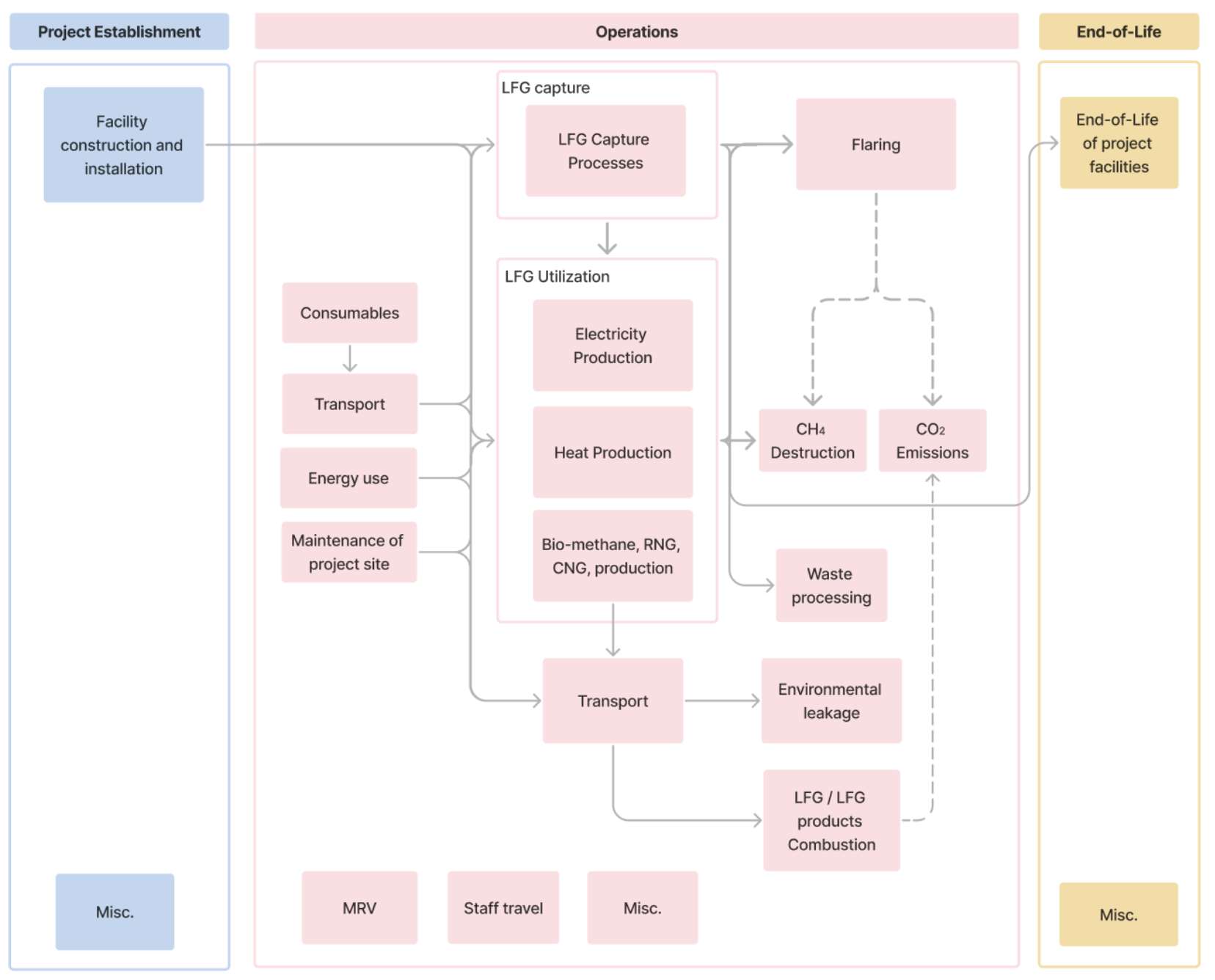 Figure 1. Process flow diagram showing system boundary for landfill methane projects
The system boundary must include all GHG SSRs from activities related to the batch of Credits delivered within the Reporting Period that are associated with the establishment of The Project, operations and end-of-life activities that occur after the Reporting Period.
Any emissions from sub-processes or process changes that would not have taken place without the involvement of the reduction, such as subsequent transportation, must be fully considered in the system boundary. This allows for accurate consideration of additional, incremental emissions induced by the reduction process.
GHG SSRs within Tables 1 and 2 deemed not appropriate to include in the system boundary may be excluded if robust justification and appropriate evidence is provided.
Table 1. Baseline System Boundary
| Activity | GHG Source, Sink or Reservoir | GHGs | Scope | Timescale |
|---|---|---|---|---|
| Baseline operations | Decomposition of waste at the SWDS site | CH4 | The anaerobic breakdown of organic waste in the landfill that produces landfill gas (mainly CH₄ and CO₂), where methane is emitted to the atmosphere or destroyed only to the extent it already happens without the project | Over each Reporting Period - must be accounted for in the relevant Reporting Period (See Section 7.2) |
| Electricity generation | All GHGs | Emissions associated with electricity supply in the absence of the project (e.g. grid / captive fossil plant) | ||
| Heat generation | All GHGs | Emissions associated with heat supply in the absence of the project (e.g. fossil boiler / furnace) | ||
| Natural gas use | All GHGs | Emissions associated with natural gas production, distribution and combustion in the absence of the project |
Table 2. Project System Boundary
| Activity | GHG Source, Sink or Reservoir | GHGs | Scope | Timescale |
|---|---|---|---|---|
| Project Establishment | Facility construction and installation | All GHGs | Equipment and materials manufacture, transport to site and construction site emissions. To include: • product manufacture emissions for equipment, buildings, infrastructure and temporary structures (lifecycle modules A1-A31). • Transport emissions associated with transporting materials and equipment to the project site(s) (lifecycle module A41). • Emissions related to construction and installation of the project site(s) (lifecycle module A51). To include energy use for construction, installation and groundworks, as well as waste processing activities and emissions associated with land use change. | Before project operations start - must be accounted for in the first Reporting Period or amortized in line with allocation rules (see Section 7.3.1) |
| Project Operations | LFG capture processes | All GHGs | Emissions associated with capturing the LFG before it is flared or used, including: • Fuel and energy use • maintenance of the project site(s), equipment, vehicles, buildings and infrastructure including activities associated with maintenance • use of consumables • waste processing | Over each Reporting Period - must be accounted for in the relevant Reporting Period (See Section 7.3.2) |
| Flaring direct emissions | CH4, CO2 | Direct emissions generated from flaring, oxidation, or other non-use forms of GHG mitigation. | ||
| LFG utilization processes | All GHGs | Emissions associated with processing and using the LFG for electricity and/or heat production, and/or injecting it natural gas pipeline, or compressed liquified, including: • Fuel and energy use • maintenance of the project site(s), equipment, vehicles, buildings and infrastructure including activities associated with maintenance (lifecycle module B2), repair (B3), replacement (B4) and refurbishment (B5)1 • use of consumables • waste processing | ||
| Transport of LFG products | All GHGs | Emissions associated with the transportation of LFG products, such as compressed / liquified LFG, to final user via e.g. trucks • Fuel and energy use • maintenance of the project site(s), equipment, vehicles, buildings and infrastructure including activities associated with maintenance (lifecycle module B2), repair (B3), replacement (B4) and refurbishment (B5)1 • use of consumables • waste processing | ||
| Environmental leakage | All GHGs | Emissions associated with unintentional leakage of LFG/biomethane in e.g. gas network / dedicated pipeline; or trucked CNG/LNG. | ||
| Staff travel | All GHGs | Flight, car, train or other travel required for The Project operations, including contractors and suppliers required on site. | ||
| MRV | All GHGs | Any embodied, energy and transport emissions associated with sampling for MRV purposes | ||
| Misc. | All GHGs | Any SSRs not captured by categories above. | ||
| Project End-of-life | End-of-life of project facilities | All GHGs | Anticipated end-of-life emissions (lifecycle Modules C1-4)1. To include deconstruction and disposal of the project site(s), equipment, vehicles, buildings or infrastructure. | After Reporting Period - must be accounted for in the first Reporting Period or amortized in line with allocation rules (See Section 7.3.3) |
The Project Proponent must consider all GHGs associated with SSRs, in alignment with the United States Environmental Protection Agency’s definition of GHGs, which includes: carbon dioxide (CO2), methane (CH4), nitrous oxide (N2O) and fluorinated gasses such as hydrofluorocarbons (HFCs), perfluorocarbons (PFCs), sulfur hexafluoride (SF6) and nitrogen trifluoride (NF3).
All GHGs must be quantified and converted to CO2e. GHGs must be converted to CO2e in the GHG Statement using the 100-yr Global Warming Potential (GWP) for the GHG of interest, based on the most recent volume of the IPCC Assessment Report (currently the Sixth Assessment Report) 2.
Miscellaneous GHG emissions are those that cannot be categorized by the GHG SSR categories provided in Tables 1 and 2. The Project Proponent is responsible for identifying all sources of emissions directly or indirectly related to project activities and must report any outside of the SSR categories identified as miscellaneous emissions.
Emissions associated with a project's impact on activities that fall outside of the system boundary of a project must also be considered. This is covered under Leakage in Section 7.3.4.
6.2.1
System Boundary Considerations
6.2.1.1
Ancillary Activities
Ancillary activities, such as supplementary research and development activities and corporate administrative activities, that are associated with a project but are not directly or indirectly related to the issuance of Credits can be excluded from the system boundary.
6.2.1.2
Materiality
Project Proponents may exclude any SSRs included in Table 2 from the final net reduction quantification if these are demonstrated to be negligible. Negligible SSRs are those which fall below a Materiality threshold based on environmental significance of less than 1% of net CO2e reduction in any given Reporting Period. The sum of negligible SSRs must not be equal or more than 1% of net reduction.
To demonstrate this, Project Proponents may utilize an economic input-output (EEIO) approach as a preliminary screening test, estimating emissions based on project financial data (e.g., CAPEX data) combined with EEIO emission factors3 4. If this screening demonstrates that emissions are below the Materiality threshold, emissions can be excluded, or can be estimated using high level estimations if included. See Section 5.0 of the Isometric GHG Accounting Module for more details on the approach and example libraries.
6.3
Baseline Scenario
The baseline scenario represents the business-as-usual condition, describing what would occur in the absence of The Project. Under this Protocol, the baseline must correspond to one of the following situations:
- Case 1: No LFG capture system is present within the project boundary. In this case, all landfill gas generated at the site is released to the atmosphere or partially oxidized by microbes in cover material.
- Case 2: An LFG capture system exists within the project boundary, but baseline destruction or use of LFG is lower than that achieved under The Project. Baseline conditions may therefore include:
- LFG vented to the atmosphere;
- LFG flared (actively or passively managed), destroyed, or beneficially used, but at a rate demonstrably lower than the recovery and destruction or use achieved through The Project activity. The resulting methane destruction must be accounted for in baseline calculations (see in Equation 3) .
If after the implementation of The Project, captured LFG will be used in equipment that was in operation prior to the implementation of The Project, the following requirements apply:
- Each item of equipment, its remaining lifetime, and any necessary supporting documentation must be recorded in The Project Design Document (PDD). The Project Proponent may estimate remaining project lifetime using one of the following three options, adapted from the CDM “Tool to determine the remaining lifetime of equipment”5.
- Use the manufacturer's information on the technical lifetime of the equipment and compare it to the date of first commissioning
- Obtain an expert evaluation
- Alternative approach that is reviewed and approved by Isometric and the VVB
- At the end of the remaining lifetime of each item of equipment, the procedure for the selection of the most plausible baseline scenario related to electricity and/or heat generation shall be updated with any applicable downward adjustment. At this time, parameters related to each item of equipment shall also be re-estimated following the procedures in this Protocol used to make the original estimation. For example, the baseline fuel may change, which will also impact the corresponding emission factor for the fuel.
7.0
Quantification of CO2e Reduction
7.1
Net Reduction Calculation
Net CO2e reduction from a Landfill Methane Project for each Reporting Period, RP, must be calculated conservatively so as to give high confidence that the estimated net CO2e was reduced.
The combined GHG reduction in CO2e is:
Equation 1
Where:
- represents the combined reduction of all GHGs for the Reporting Period, RP, in tonnes of CO2e.
- represents the net reduction of fossil CO2 emissions for the Reporting Period, RP, in tonnes of CO2.
- represents the net reduction of methane emissions for the Reporting Period, RP, in tonnes of CH4.
- represents the 100-year global warming potential of CH4. This term must be determined based on the most recent IPCC Assessment Report (AR). This value is 27.9 in the IPCC Sixth Assessment Report.
The net reduction in CH4 emissions is:
Equation 2
Where:
- represents methane that would otherwise be emitted in the absence of the project, net of baseline destruction, system losses and baseline oxidation adjustments, and is therefore equal to the methane reduction attributable to the project over the Reporting Period, RP, in tonnes of CH4
The net reduction in fossil CO2 emissions is:
Equation 3
- represents the CO2 emissions from heat, electricity or natural gas which would have occurred in the absence of The Project, over the Reporting Period, RP, in tonnes of CO2.
- represents the CO2e emissions from the associated LCA in The Project over the Reporting Period, RP, in tonnes of CO2.
7.2
Calculation of Baseline Emissions
Emissions in the baseline scenario are calculated using the following set of equations. Note that some terms in the baseline equations require inputs from The Project scenario to assess the full project impact.
7.2.1
Methane Components
The baseline methane emissions consist of direct landfill emissions. The quantity depends on the amount of methane that is flared or utilized under The Project activity, the amount that would be oxidized in the baseline scenario, and the amount that would be captured and destroyed in the baseline.
Equation 4
Where
- represents the methane that would otherwise be emitted in the absence of The Project, over the Reporting Period, RP, in tonnes of CH4
- represents methane in the LFG which is flared and/or utilized under The Project scenario over the Reporting Period, RP, in tonnes CH4.
- represents the fraction of methane in the LFG that would be oxidized in the top layer of the SWDS (unitless).
- represents the amount of methane in the LFG that would be destroyed from a pre-existing capture system and/or to meet regulatory requirements, over the Reporting Period, RP in tonnes CH4. For a baseline scenario corresponding to Case 1, this term is 0.
7.2.1.1
Captured Methane
is determined at the end of each Reporting Period as the sum of the quantities of methane flared and used in power plants, boilers, air heaters, furnaces, kilns and natural gas distribution, as follows:
Equation 5
Where:
- represents methane which is flared and/or utilized under The Project scenario over the Reporting Period, RP, in tonnes CH4.
- represents the amount of methane flared (or otherwise oxidized) over the Reporting Period, RP, in tonnes CH4
- represents the amount of methane which is destroyed for electricity generation over the Reporting Period, RP, in tonnes CH4
- represents the amount of methane which is destroyed for heat generation over the Reporting Period, RP, in tonnes CH4
- represents the amount of methane which is delivered to consumers via natural gas distribution network and/or dedicated pipeline and/or to the truck over the Reporting Period, RP, in tonnes CH4
7.2.1.2
Destruction And/or Utilization Efficiency
Flare
The destruction efficiency of methane via flaring must be determined through real-time measurement and/or applying default values following the CDM methodological tool “Project emissions from flaring”6.
is determined as the difference between the amount of methane supplied to the flare (or other oxidation system) and any methane emissions from the system, as follows:
Equation 6
Where:
- represents the amount of methane in the LFG that is flared (or otherwise oxidized) over the Reporting Period, RP, in tonnes CH4
- represents the amount of methane sent to all flares, including primary and backup flares over the Reporting Period, RP, in tonnes CH4
- represents methane emissions from incomplete destruction, in tonnes CH4. This term is determined using the CDM methodological tool “Project emissions from flaring”6. If LFG is flared through more than one flare, then this term is the sum of emissions for each flare determined separately.
Heat generation
When methane is used for heat generation, The Project must only account for the fraction of methane destroyed in the utilization equipment. The amount of methane in the LFG destroyed for heat generation in The Project, is determined as follows:
Equation 7
Where:
- represents the amount of methane which is destroyed for heat generation over the Reporting Period, RP, in tonnes CH4
- represents the amount of methane which is used for heat generation over the Reporting Period, RP, in tonnes CH4
- represents the fraction of the methane destroyed when used for heat generation in equipment type j
Electricity
LFG used to produce electricity is considered to be 100% utilized or destroyed.
Natural gas
LFG used to displace natural gas is considered to be 100% utilized or destroyed. However, physical leakage of methane prior to utilization, such as from trucking or pipelines, must be deducted.
For methane transported via mobile vehicles or dedicated pipeline, the is the amount of methane delivered to the consumer at the end of the transportation:
Equation 8
Where:
- represents the methane which is destroyed by consumers via natural gas distribution network and/or dedicated pipeline and/or to the truck over the Reporting Period, RP, in tonnes CH4
- * represents the amount of methane which is sent to consumers via natural gas distribution network and/or dedicated pipeline and/or to the truck over the Reporting Period, RP, in tonnes CH4
- represents a [loss] (#definitions-and-acronyms-losses) factor due to physical leakage during transport.
Determination of :
- Meter location adjustment: where the measurement of occurs at the point of custody transfer, i.e., is the consumer’s intake meter, any physical leakage during transport is excluded from the volume. In such cases, is set to 0.
- Infrastructure-specific factors: Project Proponents may use a loss factor that is specific to the infrastructure or equipment type used for transport. These could be manufacturer-certified fugitive emission rates for HDPE / steel pipelines; results from independent system-wide pressure-decay or leak testing; or values from industry standards.
- Regional factors: Project Proponents may use a regionally specific loss factor produced by a reputable source such as a national utility, governmental organization, or independent research organization. The Project must be located in the area for which transport loss factor was determined.
- In the absence of any of the above data, a default value of 0.1 (10%) must be applied.
, , , and are determined using the monitoring requirements described in Section 8. This includes requirements for measurement of mass flow of methane and monitoring the working hours of any power plants, boilers, air heaters, glass melting furnaces and kilns. Emission reduction may only be claimed for methane destruction during working hours that fall within the Reporting Period.
7.2.1.3
Determination of Oxidation Factor OX
Oxidation factor, , represents the proportion of methane captured by The Project activity that would have otherwise been destroyed by methanotrophic bacteria in the top layer of the landfill. Because this fraction of methane would not have been emitted to the atmosphere, it must be deducted from the quantity of methane flared or destroyed as a result of The Project.
The fraction of methane oxidized depends on cover type, moisture content, temperature, methane flux rate, and the presence of an active gas collection system. Empirical studies and IPCC guidance indicate that unmanaged or uncovered landfills typically exhibit negligible oxidation (often approximated as 0), while soil-covered landfills commonly exhibit default oxidation fractions near 0.1. Higher oxidation fractions may occur in well-managed soil covers, particularly where active gas collection reduces surface methane flux and promotes conditions favorable to methanotrophic activity. Synthetic covers generally limit oxygen diffusion and are therefore conservatively assigned an oxidation factor of 0. The default values in Table 3 reflect this literature-based range and are applied conservatively to avoid over-crediting, while accounting for differences in landfill management practices and environmental conditions. 7 8 9.
Table 3. Default counterfactual oxidation factor based on landfill age, cover type, and presence of an active gas capture system.
| Type of SWDS | Age of the SWDS cell | Type of cover material | Baseline has active gas capture system | (mean) |
|---|---|---|---|---|
| Existing SWDS | Immature and mature (less than 15 years) | No cover (Least Developed Countries (LDCs) and Small Island Developing States (SIDS)) | N/A | 0 |
| No cover (all non-LDC and non-SIDS jurisdictions) | N/A | 0.1 | ||
| Synthetic | Yes | 0 | ||
| No | 0 | |||
| Soil | Yes | 0.375 | ||
| No | 0.1 | |||
| Aged (15+ years) | Soil | Yes | 0.375 | |
| No | 0.1 | |||
| Hypothetical SWDS | N/A | Synthetic | Yes | 0 |
| No | 0 | |||
| Soil | Yes | 0.375 | ||
| No | 0.1 |
7.2.2
CO2 Components
Avoided CO2 emissions from displaced electricity, heat and natural gas due to methane utilization is determined as follows:
Equation 9
Where:
- represents the avoided CO2 emissions that would otherwise be emitted in the absence of The Project, over the Reporting Period, RP, in tonnes of CO2e
- represents the baseline emissions associated with electricity generation over the Reporting Period, RP, in tonnes of CO2e
- represents the baseline emissions associated with heat generation over the Reporting Period, RP, in tonnes of CO2e
- represents the baseline emissions associated with natural gas use over the Reporting Period, RP, in tonnes of CO2e
7.2.2.1
Calculation of CO2eEC,BL,RP
In Projects that utilize captured methane to generate electricity, the electricity generated will displace electricity generated from the grid or a captive power plant. The baseline emissions associated with electricity generation must be determined as follows:
Equation 10
Where:
- represents emissions from electricity generation in the baseline scenario, in tonnes of CO2e
- represents the electricity generated in The Project scenario, in kWhr
- represents the emissions factor of the generation source that is being replaced by The Project, in kgCO2e/kWh
If the generation source being replaced by The Project is grid electricity, The Project may apply an emission factor, , based on the following hierarchy:
- Projects may use average grid emission factors sourced from a reputable, publicly available database (e.g., IEA, or national government statistics such as US EPA, DESNZ).
- If reputable average grid factors are not available, Project must apply the following default values based on the share of renewable and nuclear energy in the electric grid:
- 0.2 kgCO2e/kWh if the share of renewables and nuclear is less or equal 33%;
- 0.1 kgCO2e/kWh if the share of renewables and nuclear is between 33% and 67%;
- 0.03 kgCO2e/kWh if the share of renewables and nuclear exceeds 67%.
If the generation source being replaced is a captive fossil fuel fired power plant, Projects must apply a default of 0.3 kgCO2e/kWh.
7.2.2.2
Calculation of CO2eHG,BL,RP
The emissions associated with heat generation in the baseline scenario are determined from the amount of methane that is used for heat generation as follows:
Equation 11
Where:
- represents emissions from heat generation in the baseline scenario, in tonnes CO2e
- represents the net calorific value of methane at reference conditions, in Terajoule per tonne CH4
- represents the ratio of The Project and baseline efficiency of the heat equipment , unitless.
- represents the amount of methane destroyed for heat in the Reporting Period, in tonnes CH4
- represents the emission intensity of the fossil fuel type used to generate heat in the equipment in the baseline scenario, in tonnes CO2e per Terajoule
is defined using the following equation:
Equation 12
Where:
- represents the efficiency of the heat equipment j used in The Project activity
- represents the efficiency of the heat equipment j used in the baseline
Project Proponents must use one of the following methods to determine (adapted from the CDM tool: Determining the baseline efficiency of thermal or electric energy generation systems10):
- Use the manufacturer’s load-efficiency function;
- Establish a load-efficiency function based measurements and a regression analysis;
- Establish the efficiency function based on historical data and regression analysis;
- Use the manufacturer’s efficiency values;
- Determine the efficiency based on measurements and use a conservative value; or
- Use a default value
7.2.2.3
Calculation of CO2eNG,BL,RP
The emissions associated with natural gas use in the baseline scenario are determined from the amount of methane that is sent to the natural gas distribution network or dedicated pipeline or to trucks as follows:
Equation 13
Where:
- represents the baseline emissions associated with natural gas use over the Reporting Period, RP, in tonnes CO2e
- represents the net calorific value of methane at reference conditions, in Terajoule per tonne CH4
- represents the amount of methane in the LFG which is sent to the natural gas distribution network or dedicated pipeline or to the trucks over the Reporting Period, RP, in tonnes CH4
- represents the average emission factor for the source of baseline natural gas consumption, in tonnes CO2e per Terajoule
7.2.3
Downward Adjustments to Baseline Activities
The baseline emissions shall be subject to a downward adjustment in alignment with the principles of the Paris Agreement Crediting Mechanism (PACM). The purpose of this adjustment is to ensure increased mitigation ambition over time and to provide a safeguard against over-crediting.
The downward adjustment, denoted as INDA in the equations below, must be applied for each calendar year after 2030 (i.e., starting in 2031). The calculation and application of the downward adjustment must adhere to the rules outlined in this section.
7.2.3.1
Methane Components
Downward adjustment to methane components must be determined based on the final use of the methane. For all methane destroyed or utilized, the downward adjusted amount of methane shall be determined in accordance with the following:
Equation 14
Where:
- is the downward adjusted amount of methane that is sent to fate in the Reporting Period, , in tonnes CH4.
- is the amount of methane that is sent to fate in the Reporting Period, , in tonnes CH4. This term is determined by Equations 5-7.
- is a standard downward factor for fate .
- is the fate of the methane such as destruction via flaring, or utilization for electricity generation, heat generation or natural gas supply.
- is the year of the current Reporting Period.
- 2030: is the reference year after which downward adjustments are applied
The downward adjustment factor is determined for each methane fate based on The Project configuration, and is expressed as a decimal factor for use in calculations.
- For projects where flaring of methane is the sole activity:
- is 0.02 (or 2%), if both of the following conditions are met:
- The amount of landfill gas captured is insufficient to continuously operate an electricity generation plant with a capacity equal to or greater than 5 MW; and
- The generation of energy or supply of gas is not financially viable, inclusive of potential revenues from emission reduction Credits.
- is 0.02 (or 2%) for a three-year period for projects that have demonstrated evidence of good-faith efforts to use methane (for energy generation or supply of gas) but have not been able to do so due to insurmountable technical or political barriers. The three year period is renewable one time (for a total of six years) contingent on demonstration of renewed good-faith efforts to use the methane. Evidence may include feasibility studies and government correspondence and is subject to VVB and Isometric’s evaluation.
- In all other circumstances, is 0.05 (or 5%).
- is 0.02 (or 2%), if both of the following conditions are met:
- For projects involving the utilization of methane (for energy generation or supply of gas) with an associated back-up flare:
- For the portion of methane that is utilized, the is 0.01 (or 1%).
- For the portion of methane sent to the back-up flare:
- if the amount of methane sent to the back-up flare represents 10% or less of the total methane utilized, is 0.01 (or 1%).
- If the amount of methane sent to back-up flare represents > 10% of the total methane utilized, the factor is determined using the same rules for flaring only projects above.
- For projects that include a primary flare system, as well as utilization of methane with back-up flaring:
- For the primary flaring system, the factor is determined using the same rules for flaring only projects above;
- For the utilization stream, and associated back-up flare, the factors are determined in accordance with the rules for utilization of methane with associated back-up flare.
Downward adjusted methane emissions calculated from Equation 13 are substituted into Equation 4 and Equation 3 to calculate the total downward adjusted baseline methane emissions in a Reporting Period.
7.2.3.2
Fossil Components for Electricity Generation, Heat Generation and Natural Gas Supply
For baseline components associated with the utilization of methane in years after 2030, including electricity generation, heat generation, and the supply of LFG or biomethane to consumers, the downward adjusted baseline emissions shall be calculated as:
Equation 15
Where:
- represents the downward adjusted baseline emissions for utilization fate in the Reporting Period, RP, in tonnes CO2e.
- represents baseline emissions for utilization fate in the Reporting Period, RP, in tonnes CO2e. This term is determined using Equations 9-12.
- represents the baseline emissions in 2030 for the component under study.
- 0.01 represents the fixed downward adjustment for the electricity generation, heat generation, and natural gas supply.
- is the year of the current Reporting Period.
- 2030: is the reference year after which downward adjustments are applied
Downward adjusted fossil emissions calculated from Equation 14 are substituted into Equation 8 to calculate the total downward adjusted fossil emissions in a Reporting Period.
7.3
Calculation of Project Emissions
is the total GHG emissions associated with a Reporting Period, RP. This can be calculated as:
Equation 16
Where
- represents the total GHG emissions for a Reporting Period, RP, in tonnes of CO2e.
- represents the GHG emissions associated with project establishment, represented for the Reporting Period, RP, in tonnes of CO2e, see Section 7.3.1.
- represents the total GHG emissions associated with operational processes for a Reporting Period, RP, in tonnes of CO2e, see Section 7.3.2.
- represents GHG emissions that occur after the Reporting Period and are allocated to a Reporting Period, RP, in tonnes of CO2e, see Section 7.3.3.
- represents GHG emissions associated with The Project’s impact on activities that fall outside of the system boundary of a project, over a given Reporting Period, in tonnes of CO2e, see Section 7.3.4.
The following sections set out specific quantification requirements for each variable.
7.3.1
Calculation of CO2eEstablishment, RP
GHG emissions associated with project establishment should include all historic emissions incurred as a result of project establishment, including but not limited to the SSRs set out in Table 2. This includes the following emissions sources:
- Equipment and materials manufacture
- Equipment and materials transport to site
- Construction and installation
- Other miscellaneous emissions not captured by the above categories.
Project establishment emissions occur from the point of project inception up until the first Reporting Period. Establishment emissions may be accounted for in the following ways, with the allocation method selected and justified by The Project Proponent:
- as a one time deduction from the first verification, or
- amortized over the first crediting period (or less) as annual emissions.
7.3.2
Calculation of CO2eOperations, RP
GHG emissions associated with must include all emissions associated with operational activities, including but not limited to the SSRs set out in Table 2.
emissions occur over the Reporting Period for the deployment being credited and are applicable to the current deployment only. emissions must be attributed to the Reporting Period in which they occur. This includes any emissions from fuel and energy use for LFG capture, destruction and utilization processes, transport and supply of methane to consumers via dedicated pipeline, any physical leakage of LFG during transportation.
7.3.2.1
Direct Emissions From CO2 Flare
Equation 17
Where:
- represents the net reduction of methane emissions for the Reporting Period, RP, in tonnes of CH4
- represents the mass ratio of CO2 produced to CH4.
The Project emissions from methane flaring must be determined through real-time measurement and/or applying default values following the CDM methodological tool “Project emissions from flaring”.
7.3.2.2
Emissions From LFG Upgrading
If LFG is upgrading to RNG occurs offsite, the emissions associated with the upgrading facility will be calculated as:
Equation 17
Where:
- represents the net reduction of methane emissions for the Reporting Period, RP, in tonnes of CH4
- represents an emissions factor associated with upgrading the LFG to RNG, in tonnes CO2/tonnes CH4.
7.3.3
Calculation of CO2eEnd-of-Life, RP
includes all emissions associated with activities that are anticipated to occur after the Reporting Period, but are directly or indirectly related to the Reporting Period. For example, this could include end-of-life emissions for The Project facility (indirectly related to all deployments).
GHG emissions associated with may occur from the end of the Reporting Period onwards, and typically through to completion of project site deconstruction and any other end-of-life activities.
GHG emissions associated with activities that are directly related to each deployment must be quantified as part of that Reporting Period. GHG emissions associated with activities that are indirectly related to all deployments may be allocated in the same ways as set out in .
7.3.4
Calculation of CO2eLeakage, RP
includes emissions associated with a project's impact on activities that fall outside of the system boundary of a project. It includes increases in GHG emissions as a result of The Project displacing emissions or causing a knock on effect that increases emissions elsewhere. For landfill gas projects, there is not a material risk of leakage associated with changes in feedstocks, defined as the materials entering the landfill, that result from the implementation of a landfill methane project. Landfill feedstocks consist of waste, and decisions about their generation and disposal are driven primarily by waste management systems and policies rather than by the presence of landfill gas capture or destruction activities. Therefore, projects are not required to assess leakage related to landfill waste streams. Isometric reserves the right to reevaluate this position if evidence emerges that landfill methane projects cause systematic changes in the type or quantity of waste disposed at landfills.
emissions may result from changes in the amount or type of landfill gas methane utilization between the baseline and project scenario. For example, if a project was collecting and using some amount of methane for on site power generation in the baseline scenario, for either on site energy needs or exporting to the grid, and under The Project a pipeline connection is built and the methane no longer goes to on site generation, that forgone power generation is a form of leakage. GHG emissions associated with replacement power needs to be assessed.
It is The Project Proponent's responsibility to identify potential sources of leakage emissions. emissions must be attributed to the Reporting Period in which they occur. Allocation may be permitted in certain instances, on a case by case basis in agreement with Isometric.
does not include physical leakage. Accounting of emissions from physical leakage from pipeline, or during truck transport, are described in Section 7.2.1.
7.3.5
Emissions Accounting Requirements
7.3.5.1
Data Collection
Project Proponents must use the most representative, accurate and plausible data that is available at the time of assessment in the GHG Statement. Activity data used to inform GHG accounting may be primary data or secondary data. Project Proponents must strive to use primary data in GHG accounting, but secondary data may be used where primary data is either not available or not practical. More details on data requirements, including data quality hierarchy and data quality principles, can be found in Section 3 of the GHG Accounting Module v1.0.
7.3.5.2
Considerations for Waste Inputs
Embodied emissions associated with system inputs considered to be waste products can be excluded from the accounting of the GHG Statement system boundary provided the appropriate eligibility criteria are met.
For waste energy inputs, for example the use of waste heat, refer to section 6.1 of the Energy Use Accounting Module v1.2.
For all other waste inputs, refer to Section 6.3 of the GHG Accounting Module v1.0.
7.3.5.3
Energy Use Accounting
This section sets out specific requirements relating to quantification of energy use as part of the GHG Statement. Emissions associated with energy usage result from the consumption of electricity or fuel.
Electricity
Examples of electricity usage may include, but are not limited to:
- Electricity consumption for LFG extraction and collection (blowers, vacuum pumps, wellfield controls);
- Gas treatment and pre-conditioning (cooling, drying, filtration, H2S or siloxane removal);
- Operation of gas upgrading systems (membranes/PSA/scrubbers) and any CNG/LNG compression or liquefaction;
- Auxiliary loads for LFG utilisation equipment (engines, generators, boilers, turbines, CHP systems);
- Operation of gas injection or dedicated pipeline systems (compressors, odorization, monitoring and control);
- Facility and building operation (lighting, HVAC, control rooms, safety and monitoring systems); and
- Electricity consumption associated with LFG handling or processing at off-site user facilities were included within the project boundary.
The following calculation approach must be used to estimate emissions from project’s electricity consumption:
Equation 18
Where:
- represents total emissions from The Project’s electricity consumption over the Reporting Period, RP, in tonnes CO2e
- represents the total electricity consumed from the grid over the Reporting Period, RP, in kWh
- represents the emission intensity of the electricity grid over the Reporting Period, RP, in kgCO2e/kWh
- * represents the transmissions and distribution grid losses factor which is set at 25% for all projects.
- represents the total electricity consumed from a non-grid generator over the Reporting Period, RP, in kWh
- represents the emission factor associated with the non-grid generator, in kgCO2e/kWh
Project may determine the emission intensity of the electricity grid, , using the following hierarchy:
- Projects may use Combined Margin (CM) emission factors from a reputable source. The suitability and technical rigor of the selected CM factor and its source will be evaluated by Isometric on a case-by-case basis during project validation.
- If appropriate CM factors are not available for the location of The Project, Project Proponent must apply one of the following default values for , based on the share of renewable and nuclear energy in the electric grid:
- 1.3 kgCO2e/kWh if the share of renewables and nuclear is less or equal 33%;
- 0.87 kgCO2e/kWh if the share of renewables and nuclear is between 33% and 67%;
- 0.44 kgCO2e/kWh if the share of renewables and nuclear exceeds 67%.
If the generation source is a captive fossil fuel fired power plant, Projects should make every attempt to gather information on the emission intensity of the technology generating the electricity. Where a specific emission intensity is not available, Projects must apply a default of 1.3 kgCO2e/kWh.
Fuels
Examples of fuel consumption may include, but are not limited to:
- Start-up and auxiliary burners using fossil fuels (e.g., natural gas, LPG, diesel);
- Pilot flames and continuous ignition systems;
- Combustion air fans, blowers, and induced-draft systems associated with stationary combustion devices;
- Fuel handling, mixing, and control systems that prepare LFG for combustion;
- Emissions from incomplete combustion (e.g., methane slip, CO, NOx) in stationary units; and
- Post-combustion flue-gas treatment systems, if powered or fuelled within the project boundary.
Section 6 of the Energy Use Accounting Module v1.3 provides requirements on how fuel-related emissions must be calculated in a Project.
7.3.5.4
Transportation Emissions Accounting
This section sets out specific requirements relating to quantification of transportation emissions as part of the GHG Statement.
Emissions associated with transportation include transportation of products and equipment as part of a Reporting Period’s activities. Examples may include, but are not limited to:
- Transportation of LFG or biomethane using trucks;
- Transport of construction materials at project establishment, or for any retrofit / maintenance required.
Section 4.2 of the GHG Accounting Module v1.0 provides requirements on how transportation related emissions must be calculated in a Project. It sets out the calculation approach to be followed depending on data types.
7.3.5.5
Embodied Emissions Accounting
This section sets out specific requirements relating to quantification of embodied emissions as part of the GHG Statement. Embodied emissions are those related to energy use or other emissions during the manufacture of equipment and materials used in a process.
Examples of project-specific materials and equipment that must be considered as part of the embodied emission calculation include but are not limited to:
- Raw materials used in the fabrication, assembly and construction of the LFG facility (if new);
- Any materials used for repair, maintenance, or retrofits;
- New process equipment (i.e., pumps, engines, turbines, gas upgrading infrastructure; etc).
- New pipelines used for LFG or biomethane transport.
Sets The GHG Accounting Module v1.0 out the approach to be followed to account for embodied emissions, including life cycle stages to be considered (Section 4.1), and data sources and emission factors (Section 3.4).
8.0
Monitoring and Documentation Requirements
This section establishes monitoring and documentation requirements necessary to ensure the accuracy, completeness, and credibility of landfill methane flare and utilization projects.
Requirements are grouped based on asset type. Landfill methane flare and utilization projects use the following assets:
- Solid Waste Disposal Facility
- Landfill Gas Capture System
- Methane Mass Flow Monitoring
- Destruction and Utilization Devices
Requirements are further organized into two categories:
- Validation requirements include evidence and documentation required at initial project registration.
- Verification requirements include ongoing evidence to be submitted for each Reporting Period.
Requirements are grounded in the following principles:
- Measurement Accuracy: Methane quantities must be measured with sufficient precision to support credible emission reduction claims. Given the high GWP of methane—27.9 times that of CO2 over 100 years—even small measurement errors can translate to significant over- or under-crediting. Requirements for calibrated flow meters, continuous methane analyzers, and standardized monitoring procedures ensure measurement uncertainty remains within acceptable bounds.
- Operational Transparency: Destruction and utilization devices must maintain documented operational records to verify that captured methane was actually destroyed or utilized rather than vented. Continuous monitoring of operational status prevents crediting of gas that bypassed destruction.
8.1
Solid Waste Disposal Facility
The following requirements must be met for the solid waste disposal facility where landfill gas is captured.
Validation Requirements
- The Project Proponent must provide the following facility identification information:
- Legal name and physical address of the solid waste disposal facility
- Legal name, address, and contact information of the facility owner/operator
- The facility's unique identifier if previously registered under any carbon credit program
- GPS coordinates of the landfill site
- The Project Proponent must provide the following waste treatment information:
- Maximum waste treatment capacity (tonnes per day)
- Age of landfill
- Cover type (synthetic, soil, open)
- Historical records of waste treatment (if available)
- The Project Proponent must describe the planned project activity, including:
- Intended capture rate
- Whether The Project involves installation of new LFG capture system or upgrade of existing LFG capture system
- If an existing LFG capture system is present, The Project Proponent must describe:
- The configuration and components of the existing system
- Historical capture rates with supporting documentation
- Historical destruction data (if capture system included active collection rather than passive venting)
- Whether the existing system will be modified, expanded, or replaced
- The Project Proponent must describe any mandatory regulations for LFG capture applicable to the facility
- To confirm regulatory compliance, The Project Proponent must provide:
- A copy of current operating permit(s)
- A summary of permit conditions relevant to LFG capture and destruction
- The compliance history for the preceding 36 months, including any notices of violation, enforcement actions, or permit exceedances
- The Project Proponent must confirm that:
- The Project does not divert organic waste from other uses to landfills for the purpose of inflating methane generation
- Non-standard waste management practices are not used to artificially inflate methane generation
8.2
Landfill Gas Capture System
Validation requirements
- The Project Proponent must describe the planned uses of captured LFG and estimate the proportion of gas directed to each end use. Eligible end uses include:
- Flaring
- Other direct oxidation technologies such as biofilters or catalytic oxidizers
- Electricity generation
- Heat generation in a boiler, air heater, kiln, or furnace
- Supply to consumers through a natural gas distribution network
- Supply of compressed or liquefied LFG to consumers via trucks
- Supply to consumers through a dedicated pipeline
- Other gainful uses of LFG not listed above (subject to approval by Isometric)
- The Project Proponent must indicate whether the primary methane mass flow quantification approach will use direct measurement or indirect monitoring via output data from a destruction device
8.3
Methane Mass Flow Monitoring
Validation Requirements
- The Project Proponent must provide a process diagram indicating all points of direct gas measurement and the type of measurements taken at each location.
Guidance: Figure 2 shows a suggested arrangement of LFG metering equipment that allows measuring wet flow with dry concentration provided the Project also measures the moisture content to perform the necessary conversions. The flow meter and gas analyzer must be installed in a configuration that ensures the sample analyzed is representative of the gas stream being measured.
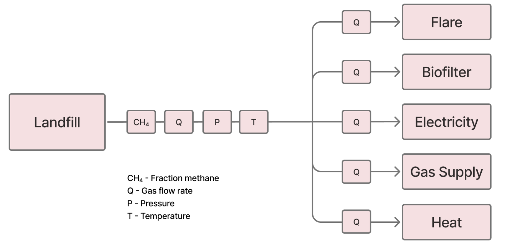 Figure 2. Example of suggested measurement locations. The number of flow meters must be sufficient to track the total flow as well as the flow to each combustion device. Image adapted from GHR003.
8.3.1
Direct Measurement
Validation Requirements
- The following parameters must be measured:
- Volumetric flow
- Temperature
- Pressure
- Methane concentration
- Optional: water content (if not measured, calculations must assume saturation)
- The measurement frequency for all in-line sensors must be recorded continuously (as an average or sum) at least every 15 minutes or totalized and recorded at least daily.
- The Project Proponent must confirm that methane mass flow measurements will adhere to the A6.4-AMT-005 methodological tool for mass flow of a greenhouse gas in a gaseous stream:
- All monitored data will be time-linked, with calculations performed using data acquired within the same time interval
- Flow measurement and gas concentration measurement will be aligned to the same moisture basis (both dry or both wet) before calculation
- All LFG flow measurements will be corrected to standard conditions: either 15.6°C (60°F) or 0°C (273.15 K) and 1 atmosphere, consistent with The Project's reporting units
- Uncertainty of the mass flow parameter will be determined by aggregating the uncertainties of all underlying measurements
- For volumetric flow in a gas stream, it is recommended that one in-line flow meter is installed per gas stream.
- If one flow meter is used for multiple gas streams for destruction and utilization
- Each device must either have an automatic valve on the inlet line that closes without manual intervention when the device is not operational, or must be designed so that gas cannot physically pass through the device while it is non-operational.
- Each destruction device must record logs of operational status (e.g., flame detector logs, energy generation data)
- The lowest verified destruction efficiency among the devices receiving LFG from the shared meter will be applied to all destruction devices monitored by that meter.
- For methane concentration in a gas stream, a continuous methane analyzer is the preferred option for monitoring methane concentrations, as the methane content of captured landfill gas can vary by more than 20% due to gas capture network conditions (e.g., dilution with air at wellheads, leaking pipes, etc.). The use of discontinuous measurements (periodic sampling) will incur a 10% uncertainty discount on the total quantity of methane collected in the sampling period. Discontinuous measurements may be used in the following cases:
- Case 1: The SWDS has a maximum waste treatment capacity of 200 tonnes per day or;
- Case 2: As a temporary backup for intermittent continuous sensor gaps for larger scale projects
- Discontinuous measurements must meet the following requirements:
- Sampling frequency must be sufficient to meet the applicable minimum precision levels, in accordance with the reliability targets defined in the UN Standard CDM-EB50-A30-STAN:
- Small scale projects must achieve 90% confidence that the estimate is within 10% of the true value
- Large scale projects must achieve 95% confidence that the estimate is within 10% of the true value
- The minimum allowable frequency is two samples per week.
- Meter readings must be collected only after the methane content has stabilized for at least 3 minutes, following national or international Protocols (e.g., ISO, ASTM) for semi-continuous analysis
- The volumetric flow must be within 20% of the average volumetric flow during the sampling period. If the volumetric flow is unstable, the sampling period is ineligible for crediting.
- Sampling frequency must be sufficient to meet the applicable minimum precision levels, in accordance with the reliability targets defined in the UN Standard CDM-EB50-A30-STAN:
- The Project Proponent must describe the SOP for maintenance, including physical inspection, calibration and field checks. The SOP must meet the following requirements:
- Cleaning and physical inspection at scheduled frequency per manufacturer specification, with activities documented by site personnel
- Field checks at a scheduled frequency using either a portable instrument or per manufacturer instruction, with % drift documented.
- Calibration by the manufacturer or a certified third-party calibration service per manufacturer’s guidance. If calibration frequency is not specified by the manufacturer, calibration must occur at minimum once every 5 years.
- The Project Proponent must describe procedures for handling field checks beyond the tolerance range of ±5%, including:
- How data will be adjusted from the previous field check to the current field check
- Application of scaling factors when field checks indicate potential over-reporting:
- For field checks that indicate under-reporting (lower flow rates, or lower methane concentration), the metered values must be used without correction.
- For field checks that indicate over-reporting (higher flow rates, or higher methane concentration), the metered values must be adjusted based on the maximum value for calibration drift recorded at the time of calibration.
- Instrument contingency plan to ensure instruments found to be out of tolerance are sent for recalibration before further use
- Portable instruments used for field checks must be maintained and calibrated per manufacturer specifications
- Portable instruments must be calibrated at least annually by the manufacturer, manufacturer-approved laboratory, or an ISO 17025 accredited laboratory
- Portable methane analyzers must be field-calibrated to known sample gas prior to each use
- The Project Proponent must confirm that:
- Flow meter calibrations will cover the range of flow rates representative of those expected at the landfill
- Methane analyzer calibrations will cover the range of conditions (temperature, pressure, concentration) representative of those measured at the landfill
- The Reporting Period end date will be no more than two months after the latest successful field check
Guidance: If a project conducts field checks quarterly during a year-long Reporting Period, then only three months of data will be subject at any one time to the adjustments above. However, if The Project Proponent chooses to conduct field checks on an annual rather than quarterly frequency, then failed events will require the penalty to be applied to the entire year’s data. Frequent calibration may minimize the total accrued drift, by zeroing out any error identified, and result in smaller overall deductions. Additionally, strong equipment inspection practices that include checking all probes and internal components will minimize the risk of meter and analyzer inaccuracies and the corresponding deductions.
Verification Requirements
- For each Reporting Period, the following parameters must be reported at each measurement point:
- Volumetric flow of the LFG stream
- Methane concentration (volumetric fraction) in the LFG stream
- Temperature of the LFG stream
- Pressure of the LFG stream
- Water content (if measured directly)
- Time stamp
- The Project Proponent must provide:
- Calculated density values
- Calculated methane mass flow
- Uncertainty analysis for the mass flow determination, propagated from volumetric gas flow, concentration and density
- Documentation of temperature and pressure corrections applied
- Documentation of moisture basis alignment
- For each monitoring instrument used during the Reporting Period, including instruments involved in field checks, The Project Proponent must provide:
- Cleaning and inspection logs
- Field check records (where applicable) showing:
- Date of field check
- Technician name and affiliation
- Percent drift documented
- As-found and as-left conditions
- Calibration certificates showing:
- Calibration date
- Calibration entity
- Calibration range
- Results demonstrating instrument accuracy
- If any field checks revealed accuracy outside ±5% threshold:
- Evidence that data was adjusted for period from last successful check to failed check
- Evidence of recalibration by manufacturer or certified service
- Last field check was within 2 months of the end of the Reporting Period (where applicable)
- For projects using a single flow meter for multiple gas streams,
- Confirm that all devices were operational
- For periods where not all devices connected to the single flow meter were optional, the following additional checks will be conducted:
- Confirm that operational devices had sufficient capacity to destroy maximum recorded gas flow
- For non-flare devices, confirm recorded output is consistent with flow of gas delivered
- For discontinuous methane measurement systems:
- Confirm that flow rate did not fluctuate by more than 20% compared to mean flow rate during sampling period
- For data gaps, gap-filling will be conducted in alignment with A6.4-AMT-005, Mass flow of a greenhouse gas in a gaseous stream:
- Substitution may be applied to either methane concentration or LFG volumetric flow, but not both parameters for the same time period
- When both parameters are missing simultaneously, substitution is not allowed unless indirect monitoring approach (Section 8.3.2) demonstrates methane destruction via output records
- Substitution for either methane concentration of LFG volumetric flow will only be used if the following conditions are met:
- When methane concentration is missing, the average LFG flow rate over gap period does not differ from the average flow over the substitution period by more than 20%
- When LFG flow is missing, the average methane concentration during gap does not differ from the average of substitution period by more than 20%
- Methane destruction or utilization continued throughout the gap period
- The following procedures will be applied based on the duration of the gap:
- Less than 6 hours: Substitute using average of 4-hour period immediately before and 4-hour period immediately after outage
- 6 to 24 hours: Substitute using the more conservative bound (upper or lower) of 95% confidence interval from 24 hours before and 24 hours after outage
- 1 to 7 days: Substitute using the more conservative bound of 95% confidence interval from 72 hours before and 72 hours after outage
- Exceeding 1 week: No substitution permitted; no methane destruction may be credited for this period
- Substitution may be applied to either methane concentration or LFG volumetric flow, but not both parameters for the same time period
- For each data gap, the following information must be provided:
- Documentation of the data gap (parameter missing, duration, timestamps)
- Evidence that conditions for substitution were met (flow/concentration stability, continued destruction)
8.3.2
Indirect Monitoring
Validation Requirements
Indirect monitoring consists of inferring methane mass flow via operational output from destruction and utilization devices. Projects may use indirect monitoring in place of direct LFG flow measurement if the following conditions are met:
- The output of a destruction device will be measured using a commercial transfer meter whose readings form the basis of an energy delivery contract
- The meter output will be converted to equivalent methane destruction volume using an appropriate conversion methodology
- The conversion methodology must be described and justified (e.g., brake specific fuel consumption calculations, conversion methodologies derived from performance testing conducted under 40 CFR Part 60 Subpart IIII, Subpart JJJJ, or Subpart KKK.)
- Commercial transfer meters will be maintained by trained personnel and serviced according to manufacturer requirements
- If The Project Proponent does not control meter maintenance, reasonable efforts will be made to obtain documentation confirming manufacturer maintenance requirements are met.
Verification Requirements
- The Project Proponent must provide:
- Commercial transfer meter readings for the Reporting Period
- Conversion calculations from meter output to methane destruction volume
- Maintenance records for commercial transfer meters (if available)
8.4
Destruction and Utilization Devices
Validation Requirements
- The Project Proponent must confirm that if operational status data are missing, that device will be treated as non-operational during the period in question, and no emission reductions will be claimed for LFG attributed to that device.
8.4.1
Flare
Validation Requirements
- The Project Proponent must describe the flare system and specify whether the flare(s) are open or enclosed. For an enclosed flare, The Project Proponent must specify whether it is a low-height flare.
- The Project Proponent must specify how the destruction efficiency will be determined:
- Direct measurement
- For open flares, a 50% default destruction efficiency will be used.
- For enclosed flares, a 90% destruction efficiency will be used, or 80% destruction efficiency for low-height flares.
- The Project Proponent must describe how operational status will be monitored and documented at minimum hourly intervals. This may include:
- Flame detection system
- Temperature measurement (for enclosed flares)
- The Project Proponent must specify which operational criterion will be used:
- Thermocouple reading above 260°C, OR
- Differential of at least 111°C between combustion temperature and ambient temperature, OR
- Alternative specification provided by the manufacturer (must be described and justified)
- The Project Proponent must describe the maintenance and calibration schedule of operational monitoring equipment, in accordance with manufacturer specifications
- The Project Proponent must confirm:
- that electric igniters are only used for start-up or flame recovery in case of flame quenching
- that no auxiliary fuels will be used (residual gas must contain sufficient flammable gas to sustain combustion)
Verification Requirements
- For each destruction device, the following operational records must be provided for the Reporting Period:
- Hourly logs of operational status and indicators, such as temperature readings
- Downtime events with timestamps and duration
- Start-up and shutdown events
- Maintenance activities and timing
- No emissions reductions can be claimed for periods of of non-operation or data gaps in operational logs
8.4.2
Heat And/or Electricity Generation
Validation Requirements
For each piece of utilization equipment used for heat or electricity generation, The Project Proponent must provide:
- The equipment baseline operation prior to the implementation of The Project
- The remaining lifetime of the equipment
- Supporting documentation using one of the following approaches (per CDM “Tool to determine the remaining lifetime of equipment”):
- Use the manufacturer's information on the technical lifetime of the equipment and compare it to the date of first commissioning
- Obtain an expert evaluation
- Alternative approach that is reviewed and approved by Isometric and the VVB
- Supporting documentation using one of the following approaches (per CDM “Tool to determine the remaining lifetime of equipment”):
- How operational status will be monitored and documented at minimum hourly intervals
- The specific criteria which defines operational status
- The destruction efficiency of the device, determined using one of the following methods adapted from the CDM tool: Determining the baseline efficiency of thermal or electric energy generation systems):
- Use the manufacturer’s load-efficiency function;
- Establish a load-efficiency function based measurements and a regression analysis;
- Establish the efficiency function based on historical data and regression analysis;
- Use the manufacturer’s efficiency values;
- Determine the efficiency based on measurements and use a conservative value; or
- Use a default value
- The maintenance and calibration schedule of operational monitoring equipment, in accordance with manufacturer specifications
- Confirmation that no auxiliary fuels will be used
Revalidation requirement
- At the end of remaining lifetime, the most plausible baseline scenario for utilization equipment must be re-assessed
Verification Requirements
- For each destruction device, the following operational records must be provided for the Reporting Period:
- Hourly logs of operational status and indicators
- Downtime events with timestamps and duration
- Start-up and shutdown events
- Maintenance activities and timing
- No emissions reductions can be claimed for periods of of non-operation or data gaps in operational logs
8.4.3
Natural Gas
Validation Requirements
For projects supplying LFG as natural gas via pipeline or trucking:
- The Project Proponent must describe the LFG upgrade and delivery pathway(s) for the LFG. Pathways may include:
- Pipeline injection: LFG upgraded and injected into natural gas transmission or distribution pipeline
- Trucking (CNG): LFG compressed and transported via truck as compressed natural gas
- Trucking (LNG): LFG liquefied and transported via truck as liquefied natural gas
- Dedicated pipeline: LFG delivered via dedicated pipeline to specific end user(s)
- The Project Proponent must provide evidence of contractual arrangements for LFG delivery:
- Gas purchase agreements with end users or aggregators
- Pipeline interconnection agreements (if applicable)
- Transportation service agreements (if applicable)
- Contracts must specify:
- Volume commitments or ranges
- Quality specifications
- Delivery points
- Term of agreement
- Pricing or payment terms
- Environmental attributes, renewable energy claims and carbon Credits belong exclusively to The Project
- Consumer Non-Claim Agreement whereby the consumer acknowledges they may not claim the gas as renewable natural gas, carbon neutral or similar. If multiple parties handle the gas, each party must confirm they will not claim environmental attributes through a Letter of Non-Claim
- The Project Proponent must indicate whether the LFG gas will be raw, partially upgraded or upgraded at the point of custody transfer
- The Project Proponent must document the quality specifications that upgraded LFG must meet, such as applicable pipeline specifications applicable transport fuel specifications.
- Projects which deliver raw or partially upgraded LFG must include the upgrading plan by the purchaser.
- There must be a binding contract for the purchaser to upgrade LFG or the purchaser must have an off-take agreement from an end-user already secured. Raw LFG cannot be transferred to intermediaries without demonstrated upgrading capability or end-use commitments.
- At each delivery point, The Project Proponent must provide the following information:
- Location
- Meter specifications: type, manufacturer, model, accuracy class
- Measurement capabilities: Volumetric flow, temperature, pressure, energy content (heating value), density (for LNG)
- Ownership/operation: Identify whether meter is owned/operated by Project Proponent, pipeline operator, end user, or independent third party
- Calibration procedures: frequency, SOP, responsible party
- Data logging and recording: data intervals, data storage and retention
- The Project Proponent must describe how an unbroken chain of custody will be maintained between LFG leaving the solid waste disposal facility to the gas purchaser.
- The Project Proponent must select an approach to quantifying transportation losses between purchaser and end-use consumer (see Section 7.2.1.2)
Verification Requirements
Proof of delivery for each end-user delivery point is required:
- The Project Proponent must report meter reading records at the point of custody transfer
- The Project Proponent must provide a chain of custody for LFG leaving the SWDS facility
- The Project Proponent must provide invoices which include the following information:
- Invoice number, date and billing period
- Seller and purchaser names and addresses
- Delivery location
- Quantity delivered, volume in standard conditions
- Time of measurement
- Unit price and total amount
- Reference to gas supply agreement
- Statement that environmental attributes are retained by the seller
- The Project Proponent must provide proof of payment for each invoice showing payment confirmation
- The total invoiced volumes must reconcile with metered delivery volumes within a ±2% tolerance
- If discrepancy >2%: Provide explanation and use conservative volume for crediting
8.4.4
Direct Use by a Third-Party
In direct use scenarios where landfill gas is delivered offsite to a third party that is not a commercial natural gas transmission or distribution system and is not under the management control of The Project Proponent, reasonable efforts must be made to obtain data that demonstrate the operational status of the offsite destruction device(s). If such data cannot be obtained, the verifier must determine, in consultation with Isometric, whether there is sufficient evidence to conclude that no significant release of project landfill gas occurred during the Reporting Period and that the destruction efficiency applied by The Project Proponent is appropriate for the end use. Evidence that may support such a determination includes, but is not limited to, the following:
- A signed affidavit from the third party operating the destruction device confirming that no catastrophic failure or significant release of landfill gas occurred during the Reporting Period, and confirming that:
- the safety features or design of the device prevent landfill gas from passing through when the device is not operational, or
- that The Project Proponent can shut off offsite gas flow in emergencies and has procedures in place to ensure immediate shutdown.
- A first person interview conducted by the verifier with the third party operator that confirms the same information in the above bullet point.
- Documents of the design specifications or safety features of the destruction device that indicate either (1) landfill gas cannot pass through the device when it is not operational, or (2) the operator is able to promptly terminate offsite gas flow in emergency situations. For (2), documentation of immediate emergency shut-down procedures must also be provided.
- Records that corroborate the type and level of operation of the destruction device during the Reporting Period, such as engine output data or other operating records. If the VVB, in consultation with Isometric, is reasonably assured that no significant offsite release of landfill gas occurred during the Reporting Period, The Project Proponent may apply the destruction efficiency associated with the offsite destruction device even if hourly operational status data are not available.
9.0
Appendix 1: Monitoring Plan Requirements
This Appendix details how The Project Proponent must monitor, document and report all metrics identified within this Module to demonstrate greenhouse gas reductions.
The Project Proponent must develop and apply a monitoring plan according to A6.4-AMT-005, for “Mass flow of a greenhouse gas in a gaseous stream” for transparency and accuracy that allows the quantification and proof of GHG emissions reductions.
Table A1-1 Parameters must be monitored for the purpose of LFG reduction and emissions accounting calculations
| Parameter | Parameter Description | Measurement Method | Monitoring Frequency | Requirement Conditions |
|---|---|---|---|---|
| Management of the SWDS | Management practices that impact anaerobic breakdown of organic waste in the landfill that produces landfill gas (CO2, CH4, NF3, N2O, SF6 or a PFC) at the SWDS site | Use different sources of data: (a) Original design of the SWDS; (b) Technical specifications for the management of the SWDS; (c) Local or national regulations | Annually | |
| CH4,EL,RP | Amount of methane in the LFG which is used for electricity generation over the Reporting Period | Directly measured using electricity meters | Continuously at least every 15 minutes | |
| CH4,sent-HG,RP | Amount of methane in the LFG which is used for heat generation over the Reporting Period | As per requirements of monitoring mass flow of a greenhouse gas in a gaseous stream | Continuously at least every 15 minutes | Uncertainties are determined based on the measuring instruments and propagated through error propagation method or Monte Carlo Simulation as per the 2019 Refinement to the 2006 IPCC Guidelines for National Greenhouse Gases Inventories |
| CH4,sent-NG,RP | Amount of methane in the LFG which is sent to the natural gas distribution network and/or dedicated pipeline and/or to the truck over the Reporting Period | Mass or volume meters, ruler gauge (that is part of daily tanks), transducers, sonar, piezoelectric devices, or fiscal meters used at the point of transfer | Continuously at least every 15 minutes or at the point of transfer | Ruler gauge must be calibrated at least once a year. Transducers, sonar and piezoelectric devices must be calibrated with the ruler gauge and receive reasonable maintenance. Any meters used as part of transfer to a third party must be maintained in accordance with local utility standards. |
| CH4,sent-flare,RP | Amount of methane sent to all flares, including primary and backup flares over the Reporting Period | As per requirements of monitoring mass flow of a greenhouse gas in a gaseous stream | Continuously at least every 15 minutes | |
| Project Operation Emissions | GHG emissions associated with operational processes for a Reporting Period | For each equipment unit j using the LFG monitor that the plant is operating in hour h by the monitoring any one or more of the following three parameters: • Temperature: Determine the location for temperature measurements and minimum operational temperature based on manufacturer's specifications of the burning equipment. Document and justify the location and minimum threshold in the PDD; • Flame: Flame detection system is used to ensure that the equipment is in operation. This option is applicable only for flares; • Products generated: Monitor the generation of steam for the case of boilers and air-heaters and glass for the case of glass melting furnaces. This option is not applicable to brick kilns | Continuous Every minute (temperature and flame detector), or every hour (products) | A value of 0 shall be assigned for the specific hour h when: a) One of more temperature measurements are missing or below the minimum threshold in hour h (instantaneous measurements are made at least every minute); b) Flame is not detected continuously in hour h (instantaneous measurements are made at least every minute); c) No products are generated in the hour h |
| Project Transport Emissions | GHG emissions associated with transportation of products and equipment part of the Reporting Period activities | Vehicle odometer, other appropriate sources | Determined once for each freight transportation activity f. To be updated whenever the distance changes | Uncertainties are determined based on the measuring instruments |
Table A1-2 Parameters must be monitored for calculating gas mass flow
| Parameter | Parameter Description | Required by the Protocol | Measurement Method | Monitoring Frequency | Requirement Conditions | Required Evidence |
|---|---|---|---|---|---|---|
| Volumetric flow of gas over time, t | Volumetric flow of the gaseous stream in time interval t on a wet or dry basis | Required | Volumetric flow meters or Instruments with recordable electronic signal (analog or digital) | Continuously at least every 15 minutes, averaged at least daily | Periodic calibration shall be performed against a primary device provided by an independent accredited laboratory. Calibration and frequency of calibration shall follow the manufacturer's specifications | Monitoring data |
| Volumetric flow of GHG gas over time, t | Volumetric fraction of greenhouse gas in a time interval t on a wet or dry basis | Required | Continuous flow meter and/or gas analyser | Continuously at least every 15 minutes, averaged at least daily | Calibration should include zero verification with an inert gas (e.g., N2) and at least one verification reading with a standard gas (single or mixed calibration gas). All calibration must be conducted in accordance with manufacturer instructions | Monitoring data |
| Volumetric fraction of gas X | Volumetric fraction of gas X in the gaseous stream during time interval t on a wet / dry basis | Required | Continuous flow meter and/or gas analyser, methane analyzer | Continuously at least every 15 minutes, averaged at least daily | Calibration should include zero verification with an inert gas (e.g., N2) and at least one verification reading with a standard gas (single calibration or mixed calibration gas). All calibration must be conducted in accordance with manufacturer instructions | Monitoring data |
| Mass flow | Mass flow of the gaseous stream in time interval t on a wet and dry basis | Required | Instruments with recordable electronic signals (analog or digital) or Calculated based on the wet-basis flow measurement and water concentration measurement | Continuously at least every 15 minutes, averaged at least daily | Periodic calibration against a primary device provided by an independent accredited laboratory is mandatory. Calibration and frequency of calibration shall follow the manufacturer's specifications | Monitoring data |
| Moisture content | Moisture content of the gaseous stream at normal conditions during time interval t | Recommended | Moisture probe, instrument, or Gravimetric determination of water content | Continuous, hourly | Uncertainties are determined based on the measuring instruments | Monitoring data |
| Temperature | Temperature of the gaseous stream during time interval t | Required | Instruments with recordable electronic signals (analog or digital), Thermocouples, thermo resistance | Continuously at least every 15 minutes, averaged at least daily | Periodic calibration against a primary device provided by an independent accredited laboratory is mandatory. Calibration and frequency of calibration is according to manufacturer's specifications | Monitoring data |
| Pressure | Pressure of the gaseous stream during time interval t | Required | Pressure meters, Pressure transducers or Instruments with recordable electronic signals (analog or digital) | Continuously at least every 15 minutes, averaged at least daily | Periodic calibration against a primary device should be performed, and records of calibration procedures should be maintained along with the primary device and its calibration certificate. Pressure transducers (either capacitive or resistive) must be calibrated monthly | Monitoring data |
| Operational status of biogas destruction devices | Operational status of biogas destruction devices | Required | Monitoring and documenting may be undertaken by recording the energy production from methane captured or by monitoring flare operation using a flame detector to confirm actual methane destruction unless another method is specified in the underlying mechanism methodology or methodological tool. | Continuous, hourly | Uncertainties are determined based on the measuring instruments | Monitoring data |
10.0
Appendix 2: Guidance for Calculating Mass Flow on a Dry and Wet Basis
When measuring mass flow of a GHG, the flow and volumetric fraction may be measured on a dry basis or wet basis. There are six possible measurement combinations, labeled A–F in Table A2-1. The Project Proponent must select the calculation methods below that align with their gas analyzer's configuration.
Table A2-1: Measurement options (Adapted from A6.4-AMT-005)
| Flow Meter Output | Flow Moisture Basis | Volumetric Fraction Basis | Calculation Option |
|---|---|---|---|
| Volume Flow | Dry | Dry or Wet | A |
| Wet | Dry | B | |
| Wet | Wet | C | |
| Mass Flow | Dry | Dry or Wet | D |
| Wet | Dry | E | |
| Wet | Wet | F |
The General Mass Flow Equation
This calculation for determining mass flow is applicable to all measurement options listed in Table 4:
Equation 17
Where
- represents the mass flow of the gas stream in time interval , in kg/h
- represents the volumetric flow of the stream in time interval on a wet or dry basis , in
- represents the concentration of the gas in stream in time interval in /
- represents the density of the GHG at the measured temperature and pressure, in
The determination of depends on the measurement equipment installed, as detailed below.
Method 1: Calculation on a Dry Basis
This method applies when the gas analyzer measures concentration on a dry basis, (Options A, B, D, E in Table 4). To use this method, the flow rate must be converted into a dry volumetric flow ().
The dry volumetric flow () is determined as follows:
- If measuring dry volume (Option A): Use the measured flow directly.
- If measuring wet volume (Option B): The moisture must be removed to determine :
Equation18
Where
- is the volumetric fraction of water ()
- and are the dry and wet volumetric flows, respectively (.
- If measuring mass flow (Options D & E): The mass flow must first be converted to a dry basis (if wet) and then converted to volume using the gas density:
Equation 19
Where:
- is the mass fraction of water ()
- and are the dry and wet mass flows, respectively (kg/h)
Equation 20
Where:
- is the volume flow on a dry bases
- is the dry mass flow as defined above
- is the density of the gas stream.
The final mass flow can be calculated by applying the general mass flow equation using the derived and the measured dry gas concentration.
Method 2: Calculation on a Wet Basis
This method applies when the gas analyzer measures concentration on a wet basis, (Options C and F in Table 4). To use this method, the flow rate must be converted into a wet volumetric flow ().
The wet volumetric flow () is determined as follows:
- If measuring wet volume (Option C): Use the measured flow directly.
- If measuring wet mass (Option F): Convert to volumetric flow using the wet gas density:
Equation 21
Where:
- is the wet volumetric flow ()
- is the measured wet mass flow ()
- is the wet gas density ().
The final mass flow can be calculated by applying the general mass flow equation (Equation 17) using the derived and the measured wet gas concentration.
11.0
Acknowledgements
Isometric would like to thank the following contributors and reviewers of this Protocol and relevant Modules:
- Katie Kaki, SCS Global Services
- Johanna Depenthal, Cool Effect
- McKenzie Wilson, Windfall Bio
- Jeff Chanton, Florida State University
12.0
Definitions and Acronyms
- ActivityThe steps of a Project Proponent’s Removal or Reduction process that result in carbon fluxes. The carbon flux associated with an activity is a component of the Project Proponent’s Protocol.
- AdditionalityAn evaluation of the likelihood that an intervention—for example, a CDR Project—causes a climate benefit above and beyond what would have happened in a no-intervention Baseline scenario.
- American Society for Testing and Materials (ASTM)A standards organization that develops and publishes voluntary consensus international standards.
- AssetAny tangible or intangible property that has value and can be owned, controlled or utilized by an individual or organization. In the context of this module, an asset refers to a physical structure.
- BaselineA set of data describing pre-intervention or control conditions to be used as a reference scenario for comparison.
- BuyerAn entity that purchases Removals or Reductions, often with the purpose of Retiring Credits to make a Removal or Reduction claim.
- Carbon Dioxide Equivalent Emissions (CO₂e)The amount of CO₂ emissions that would cause the same integrated radiative forcing or temperature change, over a given time horizon, as an emitted amount of GHG or a mixture of GHGs. One common metric of CO₂e is the 100-year Global Warming Potential.
- Carbon FinanceResources provided to projects that are generating, or are expected to generate, greenhouse gas (GHG) Emission Reductions or Removals.
- Co-productProducts that have a significant market value and are planned for as part of production.
- ConservativePurposefully erring on the side of caution under conditions of Uncertainty by choosing input parameter values that will result in a lower net CO₂ Removal or GHG Reduction than if using the median input values. This is done to increase the likelihood that a given Removal or Reduction calculation is an underestimation rather than an overestimation.
- CounterfactualAn assessment of what would have happened in the absence of a particular intervention – i.e., assuming the Baseline scenario.
- Cradle-to-GraveConsidering impacts at each stage of a product's life cycle, from the time natural resources are extracted from the ground and processed through each subsequent stage of manufacturing, transportation, product use, and ultimately, disposal.
- CreditA publicly visible uniquely identifiable Credit Certificate Issued by a Registry that gives the owner of the Credit the right to account for one net metric tonne of Verified CO₂e Removal or Reduction. In the case of this Standard, the net tonne of CO₂e Removal or Reduction comes from a Project Validated against a Certified Protocol.
- Crediting PeriodThe period of time over which a Project Design Document is valid, and over which Removals or Reductions may be Verified, resulting in Issued Credits.
- Double CountingImproperly allocating the same Removal or Reduction from a Project Proponent more than once to multiple Buyers.
- Embodied EmissionsLife cycle GHG emissions associated with production of materials, transportation, and construction or other processes for goods or buildings.
- Emission FactorAn estimate of the emissions intensity per unit of an activity.
- Emission ReductionsLowering future GHG releases from a specific entity.
- EmissionsThe term used to describe greenhouse gas emissions to the atmosphere as a result of Project activities.
- Environmental Protection Agency (EPA)A United States Government agency that protects human health and the environment.
- FeedstockRaw material which is used for CO₂ Removal or GHG Reduction.
- GHG StatementA document submitted alongside Claimed Removals and/or Reductions that details the calculations associated with a Removal or Reduction, including the Project's emissions, Removals, Reductions and Leakages, presented together in net metric tonnes of CO₂e per Removal or Reduction.
- Global Positioning System (GPS)A satellite-based navigation system.
- Global Warming PotentialA measure of how much energy the emissions of 1 tonne of a GHG will absorb over a given period of time, relative to the emissions of 1 ton of CO₂.
- Greenhouse Gas (GHG)Those gaseous constituents of the atmosphere, both natural and anthropogenic (human-caused), that absorb and emit radiation at specific wavelengths within the spectrum of terrestrial radiation emitted by the Earth’s surface, by the atmosphere itself, and by clouds. This property causes the greenhouse effect, whereby heat is trapped in Earth’s atmosphere (CDR Primer, 2022).
- International Standards Organization (ISO)A worldwide federation (NGO) of national standards bodies from more than 160 countries, one from each member country.
- Isometric Science PlatformA community resource where Project Proponents publish and visualize their early processes, Removal and Reduction data and Protocols – enabling the scientific community to share feedback and advice.
- Issuance (of a Credit)Credits are issued to the Credit Account of a Project Proponent with whom Isometric has a Validated Protocol after an Order for Verification and Credit Issuance services from a Buyer and once a Verified Removal or Reduction has taken place.
- LeakageThe increase in GHG emissions outside the geographic or temporal boundary of a project that results from that project's activities.
- Life Cycle Analysis (LCA)An analysis of the balance of positive and negative emissions associated with a certain process, which includes all of the flows of CO₂ and other GHGs, along with other environmental or social impacts of concern.
- MaterialityAn acceptable difference between reported Removals/emissions or Reductions/emissions and what an auditor determines is the actual Removal/emissions or Reduction/emissions.
- ModelA calculation, series of calculations or simulations that use input variables in order to generate values for variables of interest that are not directly measured.
- PathwayA collection of Removal or Reduction processes that have mechanisms in common.
- ProjectAn activity or process or group of activities or processes that alter the condition of a Baseline and leads to Removals or Reductions.
- Project Design DocumentThe document, written by a Project Proponent, which records key characteristics of a Project and which forms the basis for Project Validation and evaluation in accordance with the relevant Certified Protocol. (Also known as “PDD”).
- Project Design Document (PDD)The document that clearly outlines how a Project will generate rigorously quantifiable Additional high-quality Removals or Reductions.
- Project ProponentThe organization that develops and/or has overall legal ownership or control of a Removal or Reduction Project.
- Project boundaryThe defined temporal and geographical boundary of a Project.
- ProtocolA document that describes how to quantitatively assess the net amount of CO₂ removed by a process. To Isometric, a Protocol is specific to a Project Proponent's process and comprised of Modules representing the Carbon Fluxes involved in the CDR process. A Protocol measures the full carbon impact of a process against the Baseline of it not occurring.
- RPReporting Period
- RegistryA database that holds information on Verified Removals and Reductions based on Protocols. Registries Issue Credits, and track their ownership and Retirement.
- RemovalThe term used to represent the CO₂ taken out of the atmosphere as a result of a CDR process.
- Reputable SourceA source that would be widely considered trustworthy based on the process undertaken (e.g., peer review) or origin of the information (e.g., government body).
- ReservoirA location where carbon is stored. This can be via physical barriers (such as geological formations) or through partitioning based on chemical or biological processes (such as mineralization or photosynthesis).
- RetrofitThe introduction of new materials, products or technologies to an existing process or facility.
- SSRsSources, Sinks and Reservoirs
- Sensitivity AnalysisAn analysis of how much different components in a Model contribute to the overall Uncertainty.
- SinkAny process, activity, or mechanism that removes a greenhouse gas, a precursor to a greenhouse gas, or an aerosol from the atmosphere.
- SourceAny process or activity that releases a greenhouse gas, an aerosol, or a precursor of a greenhouse gas into the atmosphere.
- StorageDescribes the addition of carbon dioxide removed from the atmosphere to a reservoir, which serves as its ultimate destination. This is also referred to as “sequestration”.
- System BoundaryGHG sources, sinks and reservoirs (SSRs) associated with the project boundary and included in the GHG Statement.
- UncertaintyA lack of knowledge of the exact amount of CO₂ removed by a particular process, Uncertainty may be quantified using probability distributions, confidence intervals, or variance estimates.
- ValidationA systematic and independent process for evaluating the reasonableness of the assumptions, limitations and methods that support a Project and assessing whether the Project conforms to the criteria set forth in the Isometric Standard and the Protocol by which the Project is governed. Validation must be completed by an Isometric approved third-party (VVB).
- Validation and Verification Bodies (VVBs)Third-party auditing organizations that are experts in their sector and used to determine if a project conforms to the rules, regulations, and standards set out by a governing body. A VVB must be approved by Isometric prior to conducting validation and verification.
- VerificationA process for evaluating and confirming the net Removals and Reductions for a Project, using data and information collected from the Project and assessing conformity with the criteria set forth in the Isometric Standard and the Protocol by which it is governed. Verification must be completed by an Isometric approved third-party (VVB).
13.0
Relevant Works
Footnotes
-
Life cycle modules as described in BS EN 15978:2011 Sustainability of construction works — Assessment of environmental performance of buildings — Calculation method ↩ ↩2 ↩3 ↩4 ↩5 ↩6
-
IPCC, 2023: Climate Change 2023: Synthesis Report. Contribution of Working Groups I, II and III to the Sixth Assessment Report of the Intergovernmental Panel on Climate Change. H. Lee and J. Romero (eds.). IPCC. doi: 10.59327/IPCC/AR6-9789291691647. ↩
-
https://catalog.data.gov/dataset/supply-chain-greenhouse-gas-emission-factors-v1-3-by-naics-6 ↩
-
https://cdm.unfccc.int/methodologies/PAmethodologies/tools/am-tool-10-v1.pdf/history_view ↩
-
https://cdm.unfccc.int/methodologies/PAmethodologies/tools/am-tool-06-v1.pdf/history_view ↩ ↩2
-
United Nations Framework Convention on Climate Change. (2025). A6.4-AMM-001: Mechanism methodology—Flaring or use of landfill gas (Version 01.0). Article 6.4 Mechanism. ↩
-
Chanton, J. P., & Powelson, D. K. (2009). Methane oxidation in landfill cover soils: Is a 10% default value reasonable? Journal of Environmental Quality, 38(2), 654–663. https://doi.org/10.2134/jeq2008.0221 ↩
-
Chanton, J. P., Abichou, T., Langford, C., Hater, G., Green, R., Goldsmith, D., & Swan, N. (2011). Landfill methane oxidation across climate types in the U.S. Environmental Science & Technology, 45(1), 313–319. https://doi.org/10.1021/es101915r ↩
-
https://cdm.unfccc.int/methodologies/PAmethodologies/tools/am-tool-09-v3.0.pdf ↩
Contributors
Isometric

Kevin Sutherland, Ph.D.

Jennifer Yin, Ph.D.

Jasmin Kazazi

Michael Shell

Emma Marsland

Xueya Lu, Ph.D.

Jing He, Ph.D.

Sophie Gill, Ph.D.
Landfill Methane Flaring and Utilization © 2026 Isometric HQ Ltd is licensed under CC BY-NC-ND 4.0