Contents
1.0
Introduction
This Protocol provides the requirements and procedures for the calculation of net carbon dioxide equivalent (CO2e) removal through ex-situ mineralization of alkaline materials within an open system via Enhanced Air Capture (EAC). Within this Protocol, EAC refers to the accelerated absorption of CO2 from the atmosphere into an alkaline feedstock through an applicable removal strategy.
Open-system ex-situ mineralization (OSEM) via EAC, often referred to as surficial mineralization, is a subset of carbon mineralization CDR pathways. Projects that utilize natural rocks/minerals (e.g., silicate rocks) and industrial alkaline materials (e.g., mine tailings, steel slag, cement kiln dust, red mud, and fly ash) for long-term capture and storage of atmospheric CO2 via open-system ex-situ mineralization may use this Protocol as a framework for Crediting under the Isometric Standard. Within this Protocol, materials used for OSEM via EAC are referred to as feedstock.
Carbon mineralization, also known as mineral carbonation, is a natural process in which metal cations (such as Ca2+, Fe2+/Fe3+ and Mg2+), liberated from minerals via dissolution or surface-ion exchange, react with CO2 to form carbonate minerals. Carbon mineralization pathways are often divided into ex-situ processes, involving mineralization of a feedstock removed from its source location or formation, and in-situ processes, involving transport and injection of CO2 and other carbon sources into existing rock formations. Ex-situ mineralization may take place in closed systems, such as an engineered reactor (see CO2 Storage via Ex-Situ Mineralization in Closed Engineered Systems Module), or in open systems, such as a tailings storage facility (TSF) (as described in this Protocol).
In open systems, carbon mineralization takes place in a non-enclosed environment, where the exchange of gasses, liquids and solids materials with the surrounding environment may occur. In open systems, natural interactions with the surrounding environment, such as diffusion of atmospheric CO2 into the system, can promote conditions conducive to carbonation. These conditions are typical in surface and near-surface environments, where suitable feedstocks containing minerals such as olivine, serpentine, or basaltic rocks are exposed to the atmosphere allowing for ongoing CO2 uptake and carbonate formation. This passive influence from the surrounding environment contrasts with ex-situ mineralization that occurs in a closed, engineered system, where carbonation processes take place in a controlled environment, such as a reactor or contained facility.
This Protocol is applicable to ex-situ mineralization Projects operating in open system settings for the purpose of carbon removal via EAC. Specific applicability conditions can be found in Section 6 of this Protocol. This Protocol outlines requirements for direct measurements, monitoring and modeling of carbon removals. Requirements related to characterization of both feedstock and produced carbonated materials are outlined within Isometric’s Rock and Mineral Feedstock Characterization Module 1.0. Mineralization processes that are coupled with Direct Air Capture (DAC) are not applicable under this Protocol, Project Proponents that utilize DAC should refer to Isometrics DAC Protocol 1.1.
Project Proponents are required to meet the requirements outlined within this Protocol, as well as relevant Isometric Modules. Figure 1 displays the storage, feedstock characterization and Greenhouse Gas (GHG) Statement Modules that are linked to requirements throughout this Protocol.
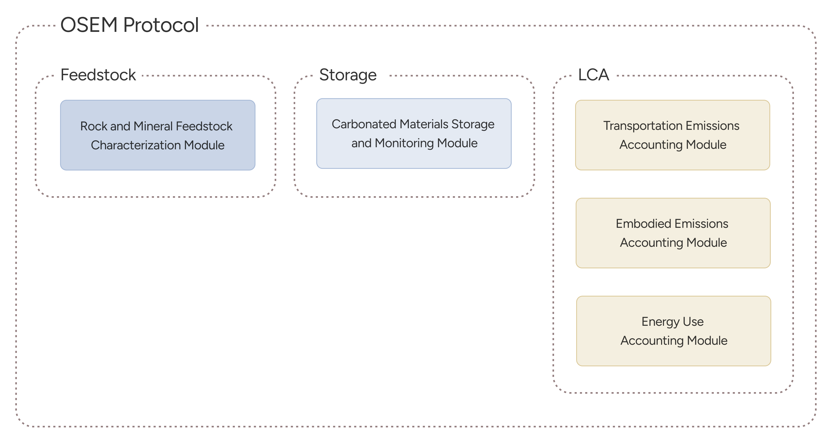
Figure 1 Storage, feedstock characterization and Greenhouse Gas Statement (GHG) Modules linked to the OSEM Protocol
2.0
Co-Benefits and Opportunities
In addition to Carbon Dioxide Removal (CDR), Projects utilizing this Protocol and accompanying Modules may generate co-benefits, including but not be limited to:
- A potential reduction in waste volumes where extractive waste is removed from a designated waste facility at a mining, or other industrial, operation for use in CDR activities.
- Increased commodity recovery from extractive wastes that would otherwise pose a risk to the environment.
- A reduction in the potential for the onset of Acid Mine Drainage (AMD) (also referred to as acid rock drainage), and/or metalliferous drainage. In locations where alkaline minerals are prevalent, they can neutralize the acidity typically associated with sulfidic minerals, effectively mitigating the risk of AMD.
- An increased social license to operate (SLO) for mining operators - CDR activities utilizing industrial alkaline by-products and/or mining wastes, may reduce the overall environmental harm associated with the storage of these materials, while also reducing the long-term costs related to management and maintenance of storage facilities.
Note: The impact of CDR activities on a project operation, and its target feedstock, must be assessed on a project-by-project basis. It is acknowledged that under certain circumstanced CDR activities may mobilise or destabilise material that was previously immobile and stable. It is the responsibility of the Project Proponent to assess the potential environmental and social impacts of CDR activities prior to Project Commencement.
3.0
Sources and Reference Standards & Methodologies
This Protocol utilizes and is intended to be compliant with the following standards and Protocols:
- Isometric Standard v1.5.0
- ISO, EN, 14064-2: 2019 - Greenhouse Gases - Part 2: Specification with guidance at the Project level for quantification, monitoring, and reporting of greenhouse gas emission reductions or removal enhancements
This Protocol is developed to adhere to the requirements of ISO 14064-2: 2019 -- Greenhouse Gas -- Part 2: Specification with guidance at the Project level for quantification, monitoring, and reporting of greenhouse gas emission reductions or removal enhancements. The Protocol ensures:
- Consistent, accurate procedures are used to measure and monitor all aspects of weathering and mineralization processes required to account for of net CO₂e removals.
- Consistent system boundaries and calculations are utilized to quantify net CO₂e removal for open system ex-situ mineralization projects.
- Requirements are met to ensure the CO₂e removals are additional.
- Evidence is provided and verified by independent third parties to support all net CO₂e removal claims.
Additional reference standards that inform the requirements and overall practices incorporated in this Protocol will include:
- ISO 14064-3: 2019 - Greenhouse Gases - Part 3: Specification with Guidance for the verification and validation of greenhouse gas statements
- ISO 14040: 2006 - Environmental Management - Lifecycle Assessment - Principles & Framework
- ISO 14044: 2006 - Environmental Management - Lifecycle Assessment - Requirements & Guidelines
Additional standards, methodologies, and Protocols that were reviewed, referenced, or for which attempts to align with or leverage in the development of this Protocol include:
4.0
Future Versions
This Protocol was developed based on the current state of the art and publicly available science regarding Open System Ex-Situ Mineralization (OSEM). As OSEM is a novel CDR approach, with limited published literature specifically related to Monitoring, Reporting and Verification (MRV) development, this Protocol incorporates requirements that may be more stringent than existing relevant regulations or other Protocols related to mineralization for CDR.
Future versions of this Protocol may be altered, particularly regarding requirements for demonstrating durability of stored carbon produced via OSEM, as the stability of CO₂ captured via dissolution, and subsequent mineralization, of suitable feedstocks becomes well demonstrated and documented; reversal risks are proven to be limited; and the overall body of knowledge and data regarding all processes, from feedstock supply to permanent storage, is significantly increased.
5.0
Regular Review and Changes in Additionality Determination
Additionality requirements are outlined in Section 2.5.3 of the Isometric Standard. Additionality determinations should be reviewed and completed every 2 years, at a minimum, or whenever Project operating conditions change significantly, such as in the following circumstances:
- Changes to Regulatory requirements or other legal obligations for Project implementation or implementation of new requirements including the introduction of new mandates, are enforced.
- Project financials indicate carbon finance is no longer required, potentially due to, for example:
- Increased fees related to payments made to the Project Proponent for utilization of waste feedstocks, or a reduction in fees relating to payments paid by the Project Proponent for utilization of waste feedstocks
- Sale of co-products that make the business viable without carbon finance
- Reduced rates for capital access
Any review and change in the determination of additionality will not affect the availability of carbon finance or carbon Credits for the current or past Crediting periods. However, if the review indicates the Project has become non-additional, the Project will be ineligible for future Credits.
6.0
Applicability
This Protocol applies to Projects or processes which:
- Use alkaline feedstocks to mineralize CO2 as carbonate minerals in open system settings.
- Use either feedstock pretreatment or physical manipulation to facilitate mineralization.
- Demonstrate that net CO2 removal occurs in excess of baseline mineralization rates.
This Protocol applies to Projects and associated operations that meet all of the following conditions:
- The Project provides a net-negative CO2 impact, as calculated in the Projects GHG statement.
- The Project is considered additional, in accordance with the requirements of Section 9.4.
- The Project provides long duration CO2 storage (> 1,000 years) in accordance with the requirements of the Carbonated Materials Storage and Monitoring Module and the Isometric Standard.
Applicable removal mechanisms include:
- Indirect carbonation - occurs in a two-step or multi-step process involving the extraction of reactive components, such as Mg2+ and Ca2+, from the host minerals. Following extraction, these components react with CO2 dissolved in porewater, facilitating carbonation through aqueous-solid interactions rather than gas-solid reactions.
Applicable storage mechanisms include:
- Solid phase storage (i.e., mineral storage) - CO2 removal and storage occurs through mineralization reactions that result in the formation of carbonate minerals. This storage mechanism constitutes a stable carbon reservoir on geological timescales (>1,000 years). This storage mechanism is eligible for Crediting under this Protocol following the monitoring requirements outlined within the Carbonated Material Storage and Monitoring Module and Section 12 of this Protocol.
- Aqueous phase storage (i.e., aqueous storage) - CO2 removal and storage in aqueous forms such as dissolved bicarbonate (HCO3-) and carbonate (CO32-) ions, creating dissolved inorganic carbon (DIC) in an alkaline solution. This occurs as CO2 interacts with water and alkaline minerals that release metal cations, which further stabilize these ions. In stable environments like deep groundwater or oceans, DIC acts as durable CO2 storage (> 1000 years), remaining in non-gaseous, dissolved forms, resistant to re-release. Studies on ocean and deep saline aquifers as natural CO2 reservoirs and analogs include refs 1 2. Refer to Section 12 for monitoring requirements regarding this storage mechanism.
Applicable Project Facilities include:
- Operational facilities that are used to store suitable alkaline material feedstocks produced as a by-product/waste in extractive or production-based industries.
- Operational alkaline Tailings Storage Facilities (TSF) containing tailings that are stored under partial saturation.
- Closed alkaline TSF containing tailings that are stored under partial saturation.
- Areas where industrial alkaline waste, such as construction debris, cement dust, and other carbon-reactive materials, are disposed of, such as landfills or other waste disposal areas.
The following feedstocks are considered applicable for use in Crediting Projects under this Protocol:
- Natural minerals and rocks, such as igneous and metamorphic rocks that are rich in alkaline earth metals. This may include:
- Mafic and ultramafic rocks, such as basalt3 and peridotite4
- Mg- and Ca-rich minerals such as wollastonite5 6, olivine 7 8 9 10 , brucite11, hydrotalcite12 and serpentine group minerals 13 14 15
- Aluminosilicates such as plagioclase [Ca-endmember anorthite; CaAl2Si2O8] 16 17
- Natural volcanic glasses 16 18
- Industrial by-products & wastes, including:
The above list is not exhaustive. Applicability criteria will be assessed on a Project-by-Project basis. Where a Project does not meet the applicability conditions outlined in this section, the Project Proponent may consult with Isometric to determine potential allowances or adjustments.
It is noted that the applicability of a feedstock, Project location and condition is dependent on the Project Proponent demonstrating compliance with the requirements outlined in the Isometric Standard, Rock and Mineral Feedstock Characterization Module 1.0, and Carbonated Materials Storage and Monitoring Module.
Under this Protocol, the following Project conditions locations are not considered applicable for Crediting:
- Operational or closed alkaline TSF that contain tailings that are stored under fully saturated or flooded conditions.
- New extractive waste storage facilities or operations within which production has increased due to the financial incentivization related to CDR Crediting or carbon financing.
- New or existing extractive waste storage facilities that contain materials/proposed feedstocks have been designated as Potentially Acid Forming (PAF) under regulatory frameworks at the Project location.
- New or existing extractive or production process waste storage facilities within which CDR processes have been implemented to meet regulatory requirements.
- Projects that are unable to demonstrate detailed baseline conditions may include Projects within which mineralization of a feedstock may occur, irrespective of the implemented removal mechanism.
Note: Facilities containing extractive waste materials designated as PAF under regulatory frameworks may be considered for Crediting under this Protocol, where a Project Proponent can demonstrate there is not an enhanced risk of acid mine (or metaliferous) drainage (AMD) as a result of Project activities. The applicability of such instances will be considered on a Project-by-Project basis by Isometric.
Further information on applicability criteria is provided in Section 7.
7.0
Scientific Overview
7.1
Removal Mechanisms
Carbon mineralization reactions can be classified as either direct carbonation or indirect carbonation. Direct mineral carbonation occurs when mineral dissolution and carbonate precipitation occurs in a single step. Indirect carbon mineralization involves multiple steps where metal cation extraction and carbonate precipitation occurs in separate steps. Direct and indirect carbonation can be carried out as either a gas-solid process or as an aqueous process. Sections 7.1.1 and 7.1.2 of this Protocol explain and summarize both reaction mechanisms. Under this Protocol, only Projects that utilize Indirect carbonation as a removal mechanism are applicable for Crediting.
7.1.1
Direct Carbonation
Direct carbonation occurs in a single step during which carbonate minerals are formed by interacting with CO2. Various reactions, depending on the feedstock, are possible.
Equations 1, 2 and 3 outline direct carbonation of serpentine, forsterite and brucite as examples for direct gas-solid carbonation:
(Equation 1)
(Equation 2)
(Equation 3)
Direct gas-solid mineral carbonation reactions can occur in either dry or humid conditions. In dry conditions, high temperatures facilitate reactions 30. In humid conditions, water-assisted reactions 31 31. Gas-solid carbonation reactions generally require high pressure, elevated temperatures, and steam for effective reaction rates 32. Under milder conditions, at lower temperatures and pressures, gas-solid carbonation has less effective reaction kinetics 33.
Direct aqueous carbonation involves the reaction of CO2 and water directly with solids. Aqueous reaction mechanisms occur when CO2 dissolved in water reacts with a mineral surface, resulting in carbonate precipitation. It is noted that silicate dissolution rates increase as pH decreases, whereas carbonate minerals are stable in alkaline conditions. To optimize carbonate precipitation without hindering silicate dissolution, as the applicable pH range is narrow, a careful balance between pH levels must be achieved.
Direct carbonation is not applicable under this Protocol as it requires precise control of reaction conditions such as temperature, pressure, and pH, which are challenging to maintain in open-system settings. In contrast, a closed, engineered system can effectively manage these conditions, making them better suited for direct carbonation processes that demand controlled environment to achieve optimal reaction rates and mineral stability.
7.1.2
Indirect Carbonation
Indirect carbonation is a multi-step process involving the dissolution of CO2 in water thereby forming carbonic acid (H2CO3). Carbonic acid reacts with rocks and minerals, releasing metal cations (e.g., Ca2+, Mg2+, Fe2+/3+) into aqueous solutions. Concurrently, the buffering of H+ ions by the process of mineral dissolution enhances the transformation of dissolved atmospheric CO2 into bicarbonate (HCO3-) and carbonate (CO32-) ions. These ions then react with the available metal cations, resulting in the formation of solid carbonate minerals.
Indirect gas-solid reaction is distinguished from direct carbonation by the additional step of cation extraction from the feedstock. This is followed by reacting the leached cations with CO2 to produce the desired carbonates. Indirect carbonation in an aqueous environment typically involves three key steps to complete the process:
- Dissolution and hydration of CO2 in aqueous solution (Equations 4, 5 and 6)
- Liberation of divalent metal cations from host minerals (Equations 7)
- Precipitation of a metal-bearing carbonate minerals and silica (Equation 8, 9, 10)
First, the dissolution of CO2 in water follows the following reaction mechanism:
(Equation 4)
Dissolution of CO2 in water forming carbonic acid (H2CO3)
(Equation 5)
The dissociation of carbonic acid into protons (H+) and bicarbonate (HCO3-)
(Equation 6)
The further dissociation of bicarbonate into protons () and carbonate ions ()
Second, the liberation of divalent metals from host minerals, take forsterite dissolution as an example:
(Equation 7)
Finally, carbonation and precipitation of metal-bearing bicarbonate, carbonates and silica, the following reactions assume formation of Mg2+-bearing carbonates:
(Equation 8)
(Equation 9)
(Equation 10)
Another illustrative example of indirect mineral carbonation is acid extraction. Acid extraction is an effective method for extracting divalent metals from unreactive silicate minerals. Acid extraction may use a range of acids including HCl, H2SO4 and HNO3. An example mechanism for acid extraction involving serpentine, a magnesium bearing silicate, and hydrochloric acid is shown in Equations 11-1333 34:
(Equation 11)
(Equation 12)
(Equation 13)
Alternative methods of indirect carbonation include molten salt extraction and sodium hydroxide extraction as well as pH swing processes 33 34.
7.2
Removal Strategies
Removal strategies are processes which lead to CDR in excess of baseline scenarios where no removal strategies have been implemented at the Project site, over the Reporting Period (RP). Requirements related to calculation of Project baselines can be found in Section 10.3.
Under this Protocol the following removal strategies are eligible for Crediting:
- Feedstock Pretreatment
- Physical Manipulation
Sections 7.2.1 and 7.2.2 of this Protocol outline and summarize the types of pre-treatment and physical manipulation methods that are applicable under this Protocol. Where Projects utilize a mixture of feedstock pretreatment and physical manipulation, the Project Proponent must refer to Section 7.2.3.
7.2.1
Feedstock Pretreatment
Project Proponents may opt to pre-treat suitable feedstock materials to enhance their reactivity. Chemical, thermal and mechanical pre-treatment methods are applicable under this Protocol. Table 1 summarizes proposed pre-treatment techniques that can accelerate ex-situ carbon mineralization of alkaline feedstocks, such as mine tailings or fly ash. The pretreatment methods outlined in Table 1 are not exhaustive. Alternative pretreatment methods may be allowable in consultation with Isometric.
Project Proponents are required to clearly outline pretreatment methodologies within the Project Design Documnet (PDD) upon submission to Isometric and the Project Validation and Verification Body (VVB). This description must include:
- Rationale for pre-treatment
- Standard Operating Procedure (SOP) or methodology used
- Physical and chemical characteristics of feedstock prior to and following pre-treatment, including, but not limited to:
- Particle Size Distribution (PSD)
- Surface area
- Total Inorganic Carbon (TIC)
Further details related to characterization requirements of project feedstocks and sampled solids can be found in the Rock and Mineral Feedstock Characterization Module 1.0 and Section 12.5.3 of this Protocol.
Table 1. Examples of applicable feedstock pretreatment removal strategies.
| Treatment Type | Treatment Method | Explanation of Treatment Method | Examples | References |
|---|---|---|---|---|
| Thermal | Thermal activation, heating | Feedstock is heated to accelerate reaction kinetics, undergo dehydroxylation, breakdown crystal structure etc. This method is particularly applicable to serpentine minerals. | Thermally treated serpentine remove hydroxyl group, resulting in chemical transformation that improves the reactivity and CO2 storage capacity of a feedstock. Pre-treatment of feedstock using high intensity electromagnetic radiation (e.g., microwave, x-rays, lasers). For example,when serpentine minerals are exposed to microwave radiation, the high-intensity energy is converted to heat that disrupts the crystal structure and transforms the mineral into an amorphous phase. The process makes Mg2+ more accessible for mineralization. | |
| Chemical | Chemical Reagent addition, acid leaching, increase CO2 concentration | The addition of chemical reagents, strong acids, and an increase in CO₂ concentration from ambient levels to flue gas or pure CO₂ can improve carbon mineralization kinetics and enhance the conversion rate of aqueous CO₂ to bicarbonate, thereby increasing overall reactivity. | Example reagents include:
| |
| Mechanical/Physical | Mineral Activation | Physical and mechanical treatment of feedstock to enhance reactivity. | Grinding feedstock to prevent surface passivation and increase reactive surface areas. The addition of abrasive particles or grinding media to optimize in-situ grinding systems, eliminate the formation of passivated layers, refresh mineral surface, enhance reactive surface area, enhance the reaction rate. |
7.2.2
Physical Manipulation
Project Proponents may choose to undertake physical manipulation of suitable feedstock to:
- Increase reactive surface area
- Enhance rate and efficiency of CO2 uptake and diffusion
- Reduce surface passivation
- Optimize gas solid contact
Table 2 summarizes physical manipulation removal strategies applicable under this Protocol. Alternative physical manipulation methods may be allowable in consultation with Isometric.
Project Proponents are required to clearly outline physical manipulation methodologies within the PDD upon submission to Isometric and the Project VVB.
Table 2. Examples of applicable physical feedstock manipulation removal strategies
| Treatment Type | Summary/Example of Treatment Method | References |
|---|---|---|
| Surface Manipulation | Surface churning: physical churning and manipulating of a feedstock in order to increase reactive surface area, disperse particles and increase the rate of CO2 uptake and diffusion. Example: Smart churning using an autonomous amphibious rover. | 60 61 |
7.2.3
Combination of Removal Strategies
Project Proponents may combine pretreatment and physical manipulation methods. Projects that utilize a combination of these removal strategies are required to identify all methods utilized to Credit under this Protocol within the Project PDD.
Projects are eligible for Crediting under this Protocol if there is sufficient evidence to demonstrate that the mechanisms and strategies utilized to achieve removals, qualify as an open-system engineered process as described in Section 1 of this Protocol.
8.1
Overarching Principles
Credits issued under this Protocol are contingent on the implementation, transparent reporting and independent verification of comprehensive safeguards. These safeguards encompass a wide range of considerations, including environmental protection, social equity, community engagement and respect for cultural values. The process mandates that safeguard plans be incorporated into all major Project phases, with detailed reports made accessible to stakeholders. Adherence to and verification of environmental and social safeguards, in accordance with Section 3.7 of the Isometric Standard, is a condition for all Crediting Projects.
8.2
Governance and Legal Framework
Project Proponents must comply with all national and local laws, regulations and policies, and receive permits from the relevant authorities, where applicable. Project Proponents must document, within the PDD, activities conducted under the Project that necessitate environmental permits. Where relevant, Projects must comply with international conventions and standards governing human rights and uses of the environment, when conducted within or foreseeably impacting party jurisdictions.
8.3
Environmental Impact Mitigation Strategies
Ongoing environmental assessments must be completed in accordance with the Isometric Standard to identify potential risks, followed by the development of tailored mitigation plans by subject matter experts where necessary. Project Proponents must first strive to avoid negative environmental impacts. To account for potential cases where adverse environmental impacts are unavoidable, the Project Proponent must develop mitigation plans to minimize and remediate adverse effects, while preventing future negative impacts. For example, this could include measures such as pollution control technologies. Effective implementation of these measures must also be accompanied by a robust monitoring plan to ensure efficacy. Project Proponents must demonstrate active stakeholder engagement throughout this process, in accordance with Section 3.5 of the Isometric Standard. All mitigation strategies must align with local and international environmental laws and contribute to sustainable Project outcomes.
8.4
Environmental Safeguards
The weathering and subsequent mineralization of rock or mineral feedstock may be associated with the release of trace metals, such as nickel (Ni) and chromium (Cr), which may pose a risk to the surrounding environment. To prevent or mitigate such risks, the Project Proponent must take the following measures:
- Comprehensive feedstock analysis must be conducted in accordance with Isometric's Rock and Mineral Feedstock Characterization Module 1.0. Project Proponents should select rock or mineral feedstocks that minimize the risk of soil and groundwater contamination.
- A robust monitoring system must be established to regularly check for potentially harmful metals in surface and groundwater. This will likely involve periodic sampling and analyses alongside field monitoring for removals. The concentration of metals in soil and water must not exceed the limits established by the local authority where the Project is located. In the absence of local regulations, the Project Proponent must adhere to standards set by the European Union (EU), the World Health Organization (WHO) or the United States Environmental Protection Agency (US EPA). Justification behind the regulatory body selection must be provided in the PDD.
- If pre-existing heavy metal concentrations exceed applicable regulatory limits or guidance (as identified in the baseline scenario), the Project may still be considered for Crediting against this Protocol. Projects utilizing extractive feedstocks (such as mining wastes) must demonstrate that the Project activities do not enhance the release of heavy metals outside of the designated Project boundaries, see Section 8.5 of this Protocol.
8.5
Extractive Industry Specific Safeguards
Where a Project utilizes extractive wastes as a removal feedstock, on an active or closed mining operation, the Project Proponent is responsible for ensuring all Project activities comply with local and regional regulations. Project Proponents are required to identify how the implementation of the Project may impact mine permitting, operation, and closure, specifically where the implementation of a Project may impact waste production volumes, waste management and the mine operators net emissions.
Where a Project is undertaken within a mining or quarrying location, the Project Proponent must monitor surface and groundwater sources within and immediately outside the Project boundary for negative environmental impacts, including but not limited to: acidic and/or metalliferous drainage into the wider environment.
Where a Project is undertaken within an active mining operation, the Project Proponent is required to engage with the operator and Engineer of Record (where appropriate), to ensure compliance with relevant environmental permitting and regulations. A Project Proponent should engage with the Engineer of Record prior to undertaking CDR activities to assess the potential impacts and suitability of undertaking CDR activities at the project location.
Under this Protocol it is permissible for a Project Proponent to submit data generated by a partner operator, where a Project is undertaken within an active extractive operation or quarry. Such data may be used for both environmental monitoring, site characterization and carbon removal quantification, as long as the data is judged as suitable for such purposes by Isometric and the project VVB. Refer to Section 12 for specific monitoring requirements.
Project Proponents are required to provide documentation that demonstrates the VVB entrusted with validating removals are able to visit the Project site to undertake inspections at agreed intervals, at a minimum of every 2 years. Where access is limited due to safety concerns of the active mine operator, the Project Proponent is required to consult with Isometric to resolve validation issues. Such resolutions may include engaging the Project’s or operation’s Engineer of Record, where applicable, or a qualified third-party, to undertake measurements required by the VVB.
Projects that store carbon as a carbonated material must meet the storage and long-term monitoring requirements outlined in Section 4.1.2.1 of the Carbonated Material Storage and Monitoring Module. Adherence to the requirements and safeguards outlined in this module must be clearly described in the PDD upon submission to Isometric and the VVB. Appendices 2 and 3 outline the key requirements of the Carbonated Material Storage and Monitoring Module.
8.6
Documentation and Permitting
The Project must consider other environmental and social impacts, and the Project Proponent must provide evidence that the Project will not cause net environmental or social harm. The Project Proponent must comply with the full requirements for the evaluation of environmental and social safeguards in accordance with the Isometric Standard, as well as any local and national permitting/regulation.
Considering all aspects of the Project from feedstock production and utilization through deposition and storage, the Project Proponent must:
- Document activities conducted under the Project which may require it to obtain permits under the relevant governmental body or regulator.
- Document activities that would require the Project Proponent to obtain any drilling permits, access agreements, or any encroachment permits under local or national guidelines.
- Provide a listing of all permits or construction approvals received or applied for related to the Project and their status under any local or national programs.
- Provide documentation of safety programs and compliance, especially as related to the production and handling of extractive waste products.
In addition to the previously listed requirements, Project Proponents are required to submit the following information in the PDD related to potential Project impacts:
- Provide information on the potential impact of the Project on biodiversity.
- Document the potential for deforestation or loss of arable land.
- Address any potential impacts of feedstock utilization on food security (where applicable).
It is the responsibility of the Project Proponent to ensure that all permitting and regulatory requirements have been fulfilled and adhered to over the duration of the Crediting period and post closure.
8.7
Socio-economic Safeguards
Projects are required to ensure social safeguarding through compliance with Section 3.7.2 of the Isometric Standard. This includes, where applicable, the undertaking of a social impact assessment (or social risk assessment). Such assessments should consider specific risks related to human health and wellbeing associated with planned or ongoing Project activities. Assessments should be included in the PDD, upon submission to the Isometric and the Project VVB, prior to Crediting.
8.8
Stakeholder Engagement
In accordance with Section 3.5 Isometric Standard, Project Proponents must demonstrate active stakeholder engagement through a Stakeholder Input Process throughout Project planning and operation, ensuring that all risk mitigation strategies contribute to sustainable Project outcomes. Local stakeholders situated in the vicinity of the Project site may contribute an in-depth understanding of the project location and provide invaluable insights and recommendations on the potential risks, necessary safeguards and specific monitoring needs. The Stakeholder Input Process must adhere to requirements outlined in Section 3.5 of the Isometric Standard, and evidence of these meetings must be submitted in the PDD.
8.9
Adaptive Management Plan
Project Proponents must include in a plan for information sharing, emergency response and conditions for stopping or pausing a deployment within the PDD. Adaptive management plans should meet/fulfill the requirements outlined in Sections 8.4 and 8.5. Plans for pausing or stopping a deployment must be in place in instances where there is a risk of:
- Regulatory non-compliance,such as:
- Danger to ecosystem health detected (such as by the local community or a government agency) or
- Pollutants/metals of concern exceeding thresholds outlined in the PDD
- Compromised health and/or safety of workers and/or local stakeholders
Where a Project Proponent does not pause removal/ deployment activities in such instances, in line with the respective Project adaptive management plan, this may result in the pausing of Credit issuance by Isometric.
9.0
Relation to Isometric Standard
The following topics are covered briefly in this Protocol due to their inclusion in the Isometric Standard, which governs all Isometric Protocols. See in-text references to the Isometric Standard for further guidance.
9.1
Project Design Document (PDD)
For each specific Project to be evaluated under the OSEM Protocol, the Project Proponent must document Project characteristics/design in a Project Design Document (PDD) as outlined in Section 3.2 of the Isometric Standard. The PDD will form the basis for Project verification and evaluation in accordance with this Protocol, and must include consideration of processes unique to OSEM Projects such as:
- Detailed feedstock characterization (refer to the Rock and Mineral Feedstock Module).
- Detailed Project boundary descriptions, which will include spatial designations of control areas within the project site. These descriptions will be required to include clear demonstration of a storage location for Projects within which carbonated materials are stored (refer to the Carbonated Materials Storage and Monitoring Module).
- Description of measurement methods for all required analyses, cross-referenced with relevant standards where applicable.
- Description of any geochemical models used to quantify processes relevant to the calculation of CO2 removal that are not directly measurable.
- A comprehensive sampling plan with demonstrated statistical significance.
- A clear outline of compliance with mining/quarrying specific permitting and regulation requirements (where applicable).
9.2
Verification and Validation
Projects must be validated and Project GHG Statement (net CO2e removal) verified by an independent third party consistent with the requirements described in this Protocol as well as in Section 4 of the Isometric Standard.
The Validation and Verification Body (VVB) must consider following requisite components:
- Validate that feedstock adheres to the requirements listed in the Rock and Mineral Feedstock Characterization Module 1.0.
- Verify that the quantification approach and monitoring plan adheres to requirements that are outlined within this Protocol.
- Verify that the Environmental & Social Safeguards requirements that will be outlined in this Protocol and the Isometric Standard are met.
- Verify that the Project is compliant with all requirements outlined in the Isometric Standard, OSEM Protocol and any relevant Isometric Modules used as part of the Project Crediting framework.
9.2.1
Verification Materiality
Within this Protocol, Materiality refers to an acceptable difference between reported removals/emissions and what an auditor determines is the actual removal/emissions.
The threshold for Materiality, considering the totality of all omissions, errors and mis-statements, is 5%, in accordance with Section 4.3 of the Isometric Standard.
Verifiers should also verify the documentation of uncertainty of the GHG Statement as required by Section 2.5.7 of the Isometric Standard. Qualitative Materiality issues may also be identified and documented, such as:
- Control issues that erode the verifier's confidence in the reported data.
- Poorly managed documented information.
- Difficulty in locating requested information.
- Noncompliance with regulations indirectly related to GHG emissions, removals or storage.
9.2.2
Site Visits
Project validation and verification must incorporate site visits to Project facilities, including control, baseline and deployment locations, in accordance with the requirements of ISO 14064-3, 6.1.4.2. This is to include, at a minimum, site visits during validation and initial verification to the Project site(s). Validators should, whenever possible, observe Project operation to ensure full documentation of process inputs and outputs through visual observation. A site visit must occur at least once during each Project validation. Additional site visits may be required if there are substantial changes to field operations over the course of a Project's validation period, or if deemed necessary by Isometric or the VVB.
The Project Proponent is required to ensure that the VVB has access to the site for all required site visits. Where an OSEM Project is undertaken on an operational or closed mining/quarrying site, it is the responsibility of the Project Proponent to ensure that access will be made available when required.
9.2.3
Verifier Qualifications & Requirements
Verifiers and validators must comply with the requirements defined in Section 4 of the Isometric Standard. In addition, teams must maintain and demonstrate expertise associated with the specific technologies of interest, including feedstock and soil (where applicable) sampling, analysis and data processing.
9.3
Ownership
CDR via mineralization is often a result of a multi-step process, including for example, mining/quarrying, transporting and deposition of waste/by product feedstocks. As a result, multiple entities may be involved in the process of removals, such as instances where a CDR technology supplier is working directly with a mining operator.
When there are multiple parties involved in the removal process, and to avoid double counting of CO2e removals, a single Project Proponent must be specified contractually as the sole owner of the Credits at the point of issuance. Contracts must comply with all requirements defined in Section 3.1 of the Isometric Standard.
Where Project Proponents have pre-existing contractual agreements (that have been agreed prior to engagement with Isometric), to undertake Credit splitting, the involved parties are required to engage with Isometric and the VVB to ensure double counting has not occurred. Such Crediting situations will be handled on a Project-by-Project basis. Credits issued by Isometric will only be issued to a single Project Proponent for a designated Crediting Project location over a Reporting Period (RP).
9.4
Additionality
The Project Proponent shall be able to demonstrate additionality through compliance with Section 2.5.3 of the Isometric Standard. The baseline scenarios and counterfactual utilized to assess additionality must be Project-specific and comply with Section 10.3 of this Protocol. In instances where reviews or changes to additionality are undertaken or required, refer to Section 5 of this Protocol.
9.5
Uncertainty
The uncertainty in the overall estimate of the net CO2e removal as a result of the Project must be accounted for. The total net CO2e removed for a specific Reporting Period, RP, (CO2eRemoval, RP), must be conservatively determined in accordance with the requirements outlined in Section 2.5.7 of the Isometric Standard.
9.5.1
Reporting of Uncertainty
Projects must report a list of all input variables used in the net CO2e removal calculation and their uncertainties, including:
- Required measurements (see Section 12).
- Data used to model and estimate aqueous losses outside the Project site boundaries.
- Emission factors utilized, as published in public and other databases used.
- Values of measured parameters from process instrumentation, such as truck weights from weigh scales, electricity usage from utility power meters and other similar equipment.
- Laboratory analyses, including analysis of rock or mineral feedstocks.
More detailed uncertainty information should be provided if available, as outlined in Section 2.5.7 of the Isometric Standard.
In addition, a sensitivity analysis that demonstrates the impact of each input parameter's uncertainty on the overall net CO2e removal uncertainty must be provided. Details of the sensitivity analysis method must be provided so that the results can be re-created. Input variables may be omitted, but should be listed, if they contribute to a < 1% change in the net CO2e removal.
9.6
Data Sharing
In accordance with the Isometric Standard, all evidence and data related to the underlying quantification of CO₂e removal and environmental and social safeguards monitoring will be available to the public through Isometric's platform. This includes:
- Project Design Document
- Greenhouse Gas Statement
- Measurements taken and supporting documentation, such as calibration certificates
- Emission factors used
- Scientific literature used
- Proof of approval for necessary permits
The Project Proponent can request certain information to be restricted (only available to authorized Buyers, the Registry and VVB) where it is subject to confidentiality. This may include:
- Emissions factors from licensed databases
- Intellectual Property (IP) related to the a Project Proponents process
- GHG data that does not contribute towards Project emission calculations
However, all other numerical data produced or used as part of the quantification of net CO₂e removal will be made publicly available.
10.0
Quantification of CO₂e Removal
Within this Section, the key requirements related to system boundaries, GHG accounting and quantification of removals are outlined.
10.1
Project Definition
Project Proponents are required to define the temporal and geographic Project boundary. The Project boundary must include all activities associated with Crediting, including areas where removal mechanisms/processes occur, removed carbon storage locations and potential reversal/loss pathways.
Where a Project activity takes place on a mining or quarry operation, a Project Proponent is required to identify the Project boundary within the existing operation. This will require detailed documentation nof Project baseline scenarios, specifically within the designated Project boundary. Projects will be required to identify control sites/locations within the Project boundary that will serve to validate baseline measurements over the course of the Crediting period. Section 12.4 of this Protocol outlines the requirements for designating a Project control plot.
Project Proponents are required to submit a detailed physical Project boundary description as part of the submitted PDD to the VVB prior to Crediting. This submission should include clear definitions of the Project site, inclusive of storage areas and potential reversal/loss pathways.
10.2
Systems Boundary & GHG Emission Scope
As outlined in Section 10.1, Projects are required to provide detailed descriptions of Project boundaries for all Crediting activities. Project boundaries delineate the scope of the Project, specifying which activities, sources, and emissions are included and excluded from the accounting and Crediting framework. The system boundary for GHG accounting sets out the GHG sources, sinks, and reservoirs (SSRs) associated with the Project boundary and to be considered in the GHG statement. A cradle-to-grave GHG statement must be prepared encompassing the GHG emissions relating to the activities outlined within the system boundary. Emissions for processes within the system boundary must include all GHG SSRs from the construction and manufacturing of any Project-specific physical site and associated equipments; closure and disposal of each site and associated equipments; and operation of each process (including feedstock production, transport, pre-treatment and sampling for MRV) to include embodied emissions of consumables in the process. Any emissions from process or sub-processes changes that would not have taken place without the CDR Project, such as subsequent transportation and refining, must be fully considered in the system boundary. Paired with exclusion of waste input emissions when the criteria are met, this allows for accurate consideration of additional, incremental emissions induced by the CDR process. The system boundary must include all SSRs controlled by and related to the Project, including but not limited to the SSRs in Table 3. If any GHG SSRs within Table 3 are deemed not appropriate to include in the system boundary, they may be excluded provided that robust justification and appropriate evidence is provided. Information related to defining a Project Reporting Period can be found in Sections 10.1 and 10.4.1 of this Protocol.
Table 3. Systems boundary and scope of activities to be included for open system ex-situ mineralization Projects
| Activity | GHG sources, sinks and reservoirs | GHG | Scope | Timescale |
|---|---|---|---|---|
| Establishment of Project | Equipment and materials manufacture | All GHGs | Embodied emissions associated with equipment and materials manufactured for Project establishment (lifecycle Modules A1-3). To include product manufacture emissions for equipment, buildings, infrastructure and temporary structures. | Before Project operations start - must be accounted for in the first Reporting Period or amortized in line with allocation rules |
| Equipment and materials transport to site | All GHGs | Transport emissions associated with transporting materials and equipment to the Project site(s) (lifecycle Module A4). | ||
| Construction and installation | All GHGs | Emissions related to construction and installation of the Project site(s) (lifecycle Module A5). To include energy use for construction, installation and groundworks, as well as waste processing activities and emissions associated with land use change. | ||
| Initial surveys and feasibility studies | All GHGs | Any embodied energy and transport emissions associated with surveys or feasibility studies required for establishment of the Project site. | ||
| Misc. | All GHGs | Any SSRs not captured by categories above, for example staff transport. | ||
| Operation | Feedstock sourcing | All GHGs | Quarrying, crushing and grinding (including additional processing steps such as drying) activities including the following emissions sources:
| Over each Reporting Period - must be accounted for in the relevant Reporting Period (See Section 10.4.1) |
| Feedstock characterization | All GHGs | Embodied, energy use and transport emissions associated with sampling the feedstock for physical and geochemical characterization | ||
| Feedstock Pre-Treatment | All GHGs | Embodied, energy use and transport emissions associated with the pre-treatment of feedstocks. This should include:
| ||
| Feedstock transport to the application site | All GHGs | Transporting the feedstock material from the operational facilities or quarrying site to the deployment area - this only applies if the feedstock is transported away from its intended end of life location for the purpose of CDR | ||
| Physical manipulation of feedstock | All GHGs | Embodied, energy use and transport emissions associated with the physical manipulation of feedstocks. This should include:
| ||
| Sampling and analysis | CO2 | Sampling and analysis activities, including:
| ||
| Land use change | CO2 | Additional land use change as a result of Project expansion (not in the industrial footprint). | ||
CO2 stored | CO2 | The gross amount of CO2 removed and durably stored via ex-situ mineralization over a Reporting Period | ||
| Misc. | All GHGs | Any GHG SSRs not captured by categories above, for example: field surveys. | ||
| End of Life | End-of-life of Project facilities | All GHGs | To include anticipated end-of-life emissions (lifecycle Modules C1-4) associated with deconstruction and demolition, transport, waste processing and disposal of any equipment, buildings or infrastructure. | After Reporting Period - must be accounted for in the first Reporting Period or amortized in line with allocation rules (See Section 10.4.1) |
| Closure of storage site | All GHGs | Closure of storage site, including embodied emissions associated with equipment and materials manufacture, transport of equipment and materials to site and emissions associated with energy use and consumables use for closure operations including installation and groundworks, as well as waste processing activities and emissions associated with land use change. | ||
| Misc. | All GHGs | Any emissions source, sink or reservoir not captured by categories above. |
The Project Proponent must consider all GHGs associated with SSRs, in alignment with the United States Environmental Protection Agency’s (EPA) definition of GHGs, which includes: carbon dioxide (CO2), methane (CH4), nitrous oxide (N2O) and fluorinated gasses such as hydrofluorocarbons (HFCs), perfluorocarbons (PFCs), sulfur hexafluoride (SF6) and nitrogen trifluoride (NF3). For CO2 stored, only CO2 shall be included as part of the quantification. For all other activities all GHGs must be considered. For example, the release of CO2, CH4, and N2O is expected during diesel consumption.
All GHGs must be quantified and converted to CO2e in the GHG statement using the 100-yr Global Warming Potential (GWP) for the GHG of interest, based on the most recent volume of the IPCC Assessment Report (currently the Sixth Assessment Report).
Miscellaneous GHG emissions are those that cannot be categorized by the GHG SSRs categories provided in Table 3. The Project Proponent is responsible for identifying all sources of emissions directly or indirectly related to Project activities and must report any outside of the SSRs categories identified as miscellaneous emissions.
Emissions associated with a Project's impact on activities that fall outside of the system boundary of a Project must also be considered.
10.2.1
System Boundary Considerations
10.2.1.1
Ancillary Activities
Ancillary activities (such as supplementary research and development activities and corporate administrative activities) that are associated with a Project but are not directly or indirectly related to the issuance of Credits can be excluded from the system boundary.
10.2.1.2
Secondary Impacts on GHG emissions
OSEM may have additional impacts on GHG emissions beyond the scope of this Protocol. For example, there may be the potential for reduced GHG emissions relating to carbonate dissolution in the presence of AMD, in an instance where OSEM processes delay/restrict the onset of sulfide oxidation within waste facilities. These potential secondary climate effects are uncertain at this time and are not covered by this Protocol version.
10.2.1.3
Considerations for Project Activities Integrated into Existing Practices
Emissions associated with activities that occurred and will continue to occur without the Project may be excluded from the system boundary. For example:
- Existing electricity consumption of a mining or quarrying operations.
- Emissions from the use of pre-existing shared transportation infrastructure, such as roads, railways, or conveyor systems if there is no additional transportation infrastructure use associated with the Project.
- Emissions from the shared use of equipment and integrated processing facilities. However, any additional activities beyond normal operations under a baseline scenario must be accounted for.
- Feedstock transport: When feedstocks are used at their intended end-of-life location, such as being deployed at an existing tailings storage facility (TSF), transportation emissions can be excluded, as the material remains within its designated final use site.
10.2.1.4
Considerations for Waste Input Emission
Embodied emissions associated with system inputs considered to be waste products can be excluded from the accounting of the GHG Statement system boundary provided the appropriate criteria are met.
For waste energy inputs, for example the use of waste heat, refer to the Energy Use Accounting Module 1.2.
For all other waste inputs, the following eligibility criteria (EC) shall be considered. If EC1, in Table 4, is satisfied, embodied emissions associated with the waste product input can be excluded from the system boundary. Market leakage emissions associated with waste inputs may also be excluded from the system boundary, as compliance with EC1 would result in no change to the waste producer behavior (i.e. no market leakage) and indicates there are no alternative users of the waste product (i.e. no replacement emissions).
If EC1 is not satisfied, but both EC2 and EC3 in Table 4 are satisfied, embodied emissions associated with the waste product input can be excluded from the system boundary. Market leakage emissions associated with waste inputs may also be excluded from the system boundary, as compliance with EC2 and EC3 would result in no significant change to the waste producer behavior (i.e. no market leakage) and there are no alternative use cases for the waste product (i.e. no replacement emissions).
Table 4. Waste input emissions exclusion criteria, EC1, EC2 and EC3
| Eligibility Criteria | Description | Documentation required | |
|---|---|---|---|
| EC1 | No payment was made for the material or access, or only a “tipping fee” is paid. | Feedstock purchase, removal, or access agreement records between Project Proponent and feedstock supplier demonstrating price paid, amount, buyer, seller and date. Additionally, a signed affidavit from the feedstock supplier stating that no in-kind compensation was made to the feedstock supplier must be provided. | Or an signed affidavit from the feedstock supplier stating that no payment was made for the material or access and no in in-kind compensation was made. |
| EC2 | The amount of the waste product used by the CDR Project was not already being utilized as a valuable product by another party for non-CDR uses. Therefore, the producer of the waste product has no alternative use case for the waste product. | Feedstock purchase, removal, or access agreement records between Project Proponent and feedstock supplier demonstrating price paid, amount, Buyer, seller and date. Additionally, an affidavit from the waste supplier identifying that there are no alternative use cases for the waste product. | |
| EC3 | Payments for the waste product do not constitute a significant share of upstream operations revenue for the waste producer. | Feedstock purchase, removal, or access agreement records between Project Proponent and feedstock supplier demonstrating price paid, amount, Buyer, seller and date. Additionally, a purchase agreement of waste material that documents that payments from the Project do not constitute a large share of upstream operations revenue must be provided. |
10.2.1.5
Co-product Emission Allocation
OSEM processes may be part of a wider mining, quarrying or industrial operation, which may result in the production of co-products such as metal commodities. In this Protocol co-products are defined as products that have a significant market value and are planned for as part of production. By-products are materials of value that are produced incidentally or as a residual of the production process and are not considered here.
To allocate Project emissions associated with CDR and co-product(s), the Project Proponent may use one or a combination of, where relevant, the following co-product allocation procedures outlined below.
Procedure 1: Allocate all emissions to CDR
Projects may opt to allocate all Project emissions to CDR. The co-product(s) must still comply with all relevant emission accounting regulations and requirements, which may mean emissions are double counted. Removals must not be double counted.
Note: This is the most conservative approach to take.
Procedure 2: Divide the process into sub-processes
Where possible, the process may be divided into sub-processes. For example it may be possible to isolate processes relating to processing of the co-product, or the OSEM process may be a retrofit/part of an existing process.
Eligibility criteria, evidence requirements and GHG system boundary considerations are set out in Table 5. One of EC4 or EC5 must be satisfied in order to divide the process into sub-processes.
Table 5. Procedure 2 Eligibility Criteria, EC4 and EC5
| Eligibility Criteria | Description | Documentation required |
|---|---|---|
| EC4 | Ex-situ mineralization processes is a retrofit to an existing facility that was operable prior to the introduction of the CDR process. The purpose of the existing facility must not have been CDR prior to retrofit. | Records of existing facility activities dating back 3 years must be provided for major infrastructure Projects where a planning application was required. For all other Projects, records of the existing facility activities dating back 6 months is required. The distinction between major infrastructure Projects and other Projects is to ensure that the ex-situ mineralization process is a retrofit, as major infrastructure Project construction may be staged over many years. The GHG system boundary in this case is limited to materials and processes necessary for the retrofit and processes that directly contribute to ex-situ mineralization, including existing processes at the facility that are operated at increased capacity and additional load bearing structures. Evidence of fractional differences in inputs, for example the step-change in energy requirements for the addition of an Ex-Situ Mineralization process as a retrofit to an existing facility, must be evidenced in full. |
| EC5 | The process has components and operations that are physically separate from one another. | Evidence of separation, for example engineering diagrams showing separate equipment or electricity metering systems for separate components of the process. Sub-processes that can be isolated from the CDR process and do not contribute to CDR may be excluded from the system boundary. |
Procedure 3: Substituting emissions
Project Proponents may substitute the co-product emissions with emissions for an equivalent product and subtract these from total Project GHG emissions. When undertaking this approach the full facility GHG emissions must be included within the system boundary before substitution takes place. In practice, the co-product emissions are substituted with emissions for an equivalent product and subtracted from total Project GHG emissions.
The calculation approach to be followed is set out below:
-
Report the quantity and type for all marketed co-products produced within the Project system boundary.
-
Identify the use of the co-product and the appropriate alternative product (the “substitute product”) considering the product qualities and specific use case.
-
Determine the emissions intensity associated with the substitute product, in line with the following requirements:
- Where multiple similar substitute products with variable emissions intensities are available, the most conservative substitute product must be selected. This is the substitute product with the lowest emissions intensity.
- If the use of the product is electricity generation which is supplied to the grid, then the emissions intensity associated with the substitute product will be the average grid intensity of the region for the most recent year.
- The emissions intensity associated with the substitute product must be conservative, from a Reputable Source and approved by Isometric ahead of verification.
- Where the product will be subject to policy or regulatory requirements, for example in relation to tax Credits or to satisfy specific marketing claims, the most conservative threshold for emissions intensity shall be selected.
-
The quantity of merchantable co-products sold should be multiplied by the approved substitute product emissions intensity factor to determine the total substituted emissions.
-
The total substituted emissions should be subtracted from (see Section 10.5). Both the gross Project emissions, and the adjusted Project emissions post-substitution must be documented.
In order to ensure that the substitution method yields a conservative result, the following safeguards are in place:
- Only one co-product may be used for substitution. This should be the primary co-product, meaning the co-product which results in the highest revenue stream and is not CDR.
- Only substitution factors approved by Isometric may be used. Isometric approved substitution factors will include factors used in government regulation, provided such factors are conservative.
- The outcome of step 4 must not result in higher emissions than the gross Project emissions.
Procedure 4: Carbon mass balance if the co-product leads to Crediting
Physical allocation based on carbon mass balance shall be used in instances where the co-product leads to Crediting for CDR with Isometric. This is so that emissions are distributed according to the CO₂ balance output of the system. The requirement for Crediting to be with an Isometric Project ensures that co-product allocation can be traced and verified appropriately and according to the same set of allocation and emissions accounting requirements. The co-product allocation between CDR products can be made after process subdivision and substitution has taken place.
10.3
Baselines
Baselines are required to be quantified in line with Section 2.5.2 of the Isometric Standard. The baseline scenario for OSEM Projects assumes no activities associated with the Project have taken place, and assumes that business-as-usual industrial practices occur. A Project Proponent is required to quantify counterfactual carbon removals from the atmosphere that would have been durably stored (>1,000 years) as a result of natural/passive weathering under baseline conditions. Measurements and modeling used to quantify a Project's counterfactual under baseline conditions should be carried out in line with Section 12 of this Protocol.
As the rate of carbon mineralization process occurs is variable and can be affected by climate, seasonal change, weather systems and infrastructure design, a Project-specific baseline (counterfactual) must be established. In addition, baseline measurements should be carried out both prior to Project implementation and throughout the Project duration. Baseline monitoring should be carried out on a designated control plot, within the Project deployment area. Counterfactual measurements should take place over the same Reporting Period as the Crediting measurements, at the same temporal and spatial frequency and density, refer to Section 12.4.
A Project's counterfactual under baseline conditions is required to calculate CO2e net removal over a Reporting Period (RP), in line with the guidance outlined in Section 10.5 of this Protocol. Project Proponents are required to clearly define baseline scenarios and counterfactual quantification within the PDD upon submission to Isometric and the Project VVB.
10.4
Net CDR Calculation
This Section outlines the required quantification framework for calculating net CDR removal from a Project. This Section also outlines how Project Proponents must designate a Reporting Period (RP) and quantify emissions within outlined CDR calculations.
10.4.1
Calculation Approach and Reporting Period
OSEM typically involves the utilization of processed materials as a substrate for CO₂ removal and storage. This process begins with the sourcing of raw materials, which may require transportation, processing (e.g., grinding) and activation before they are suitable for mineralization. A combination of chemical and physical measurements are then used to quantify the total CO₂ removals over a period of time.
The for OSEM represents an interval of time over which CO₂ removals are quantified and reported for verification. Monitoring of CO2 removals must include a combination of discrete sampling (e.g., TSF sampling) and/or continuous monitoring techniques. The formulas used to calculate net within this Protocol account for all greenhouse gas (GHG) emissions associated with Project activities, as well as CO₂ removals that occur as a direct result of Project intervention over the . Net carbon removals must be calculated based on monitoring of a Project’s deployment area (Section 12) and counterfactual deductions based on baseline scenario measurements over the .
Note: In most cases, this will be an interval of time bounded by sampling events. Project Proponents are required to clearly define sampling intervals and RPs for Crediting Projects within the PDD. Data submitted for a defined RP must clearly outline the GHG emissions accounted for in that period, as well as counterfactual measurements taken from the defined Project control plot, (Section 12.4.1.3).
GHG emissions calculations must encompass all emissions related to or allocated to the Project activities during the . This may include:
- Any emissions linked with the initial setup of the Project, such as preprocessing of the materials allocated to the RP;
- Emissions occurring within the RP itself from, for example, land use change emissions and operational Project emissions;
- Anticipated emissions expected after the RP but attributed to it; such as land use change that leads to increased CO2 release over time. In this way, emissions beyond RP will still be accounted for;
- Leakage emissions that happen outside of the Project boundary due to induced market shifts associated with the RP;
The guidelines for assigning emissions to Reporting Periods are detailed in Section 10.2.
10.5
Calculation of CO2e Removed, RP
from OSEM Projects within individual Reporting Periods (RP) can be calculated as follows. A Project's is quantified by calculating the gross quantity of CO2 removed in the Project scenario, subtracting the loss portion and accounting for the total GHG emissions associated with the Project in a predefined Reporting Period. The final Quantification must be conservatively determined and supported with solid evidence (e.g., data and geochemical models), giving high confidence that, at a minimum, the reported amount of CO2e was removed. Equation 14 outlines the basic framework for quantification of net Project removals over a set Reporting Period ().
(Equation 14)
Where:
- is the total quantity of net CO2e removal for the Reporting Period, RP, in tonnes of CO2e
- is the total quantity of CO2 removed from the atmosphere based on quantification measurements for the RP, in tonnes of CO2e
- is the total counterfactual CO2 removed from the atmosphere and stored as inorganic carbon in the soil or aqueous form for the RP, in tonnes of CO2e
- is the total GHG emissions for the RP, in tonnes of
Note: Reversals occur after Credits have been issued so are not included in this equation. See Section 12.2 and Section 5 of the Isometric Standard for further information.
10.5.1
Calculation of CO2e Stored, RP
is calculated as:
(Equation 15)
Where:
- is the amount of CO2 removed from the atmosphere as a result of OSEM processes. The value for this parameter may come from direct measurements of the mineralized material and process water in the vicinity of mineralization, or through gas phase measurements (provided that the mineralization setting is reasonably isolated from other significant sources or sinks of CO2 such as biological respiration and photosynthesis).
- is representative of the inorganic carbon lost due to (bio)geochemical processes for the Reporting Period, RP, as well as downstream riverine and marine, in tonnes CO2e. This term will primarily pertain to Projects seeking Credits for carbon stored as dissolved inorganic carbon (DIC) that may leave the Project site, and may include processes such as non-carbonic acid neutralization and losses due to carbonate system re-equilibration in rivers or oceans.
10.5.1.1
Options for Quantifying OSEM Removals
Project Proponents have two options for quantification and validation of OSEM removals:
Quantification Option 1 - Quantification with solid- and aqueous-phase geochemical measurements and local validation by gas-flux measurements
Quantification Option 2 - Quantification with gas-flux measurements and local validation by solid- and aqueous-phase geochemical measurements
Project Proponents should consider aspects such as signal-to-noise ratios, inherent heterogeneity of feedstock and other relevant Project site environmental factors when choosing their primary quantification medium. These quantification and validation options are addressed in detail in the sections that follow.
10.5.1.2
Quantification Based on Solid and Aqueous Measurement (Quantification Option 1)
Equation 16 outlines the calculation of for Projects that quantify removals using Quantification Option 1:
(Equation 16)
Where:
- is the total quantity of CO2 stored via mineral storage during a Reporting Period, in tonnes of CO2e;
- is the total quantity of CO2 stored via aqueous phase storage during a Reporting Period, in tonnes of CO2e. This term implicitly includes any non-carbonic acid neutralization that may occur in the Project site.
- is the total amount of that is expected to be released back to the atmosphere due to outgassing in river systems, in tonnes of CO2e;
- is the total amount of that is expected to be released back to the atmosphere due to outgassing in the ocean, in tonnes of CO2e;
- is the total amount of that is expected to be released back to the atmosphere not in the categories above, such as through dissolution of carbonates by interaction with acidic fluids, in tonnes of CO2e.
The Project Proponent is eligible to Credit for CO2 removal when can be fully accounted for by CO2 storage in both the mineral and aqueous phases. Project Proponents must follow the monitoring, measurement and modeling approaches outlined in Section 12 of this Protocol.
Additionally, it is noted that a Project Proponent must consider relative uncertainty around reporting aqueous storage over a Reporting Period. To claim aqueous removals, a Project Proponent is required to consider downstream losses (see Section 12.5.2).
Below is a brief overview of how each term in Equation 16 is determined, with more details provided in Section 10.5.2 to Section 10.5.7.
represents the amount of CO2e that is stored in the mineral phase over the course of the Reporting Period. This term must be determined through direct measurement of representative samples that are collected from the Project site. Guidance for representative sampling can be found in Section 4 of the Rock and Mineral Feedstock Characterization Module 1.0. Analytical methods that quantify carbon content, carbonate mineral type and abundance are acceptable for determining (see Section 12.5 for details) .
(Equation 17)
Where:
- the amount of CO2 stored as carbonate minerals at time point t, in tonnes. will be determined from the difference in carbonate content from the beginning to the end of a Reporting Period.
is the amount of CO2e that is stored in the aqueous phase (as dissolved inorganic carbon) over the course of the Reporting Period. This includes all aqueous phase alkalinity that will be exported from the Project site to groundwater, rivers and ultimately the ocean. may be determined by characterization of representative samples of porewater, ground water or process water within and beneath the region in which active mineralization is occurring. Characterization of representative aqueous phase samples will include either direct measurement of multiple carbonate system variables or direct measurements of cation and anion abundances (see Section 12.5). Since this term considers either the dissolved inorganic carbon present or the cation and anion abundance in fluids, this term implicitly considers the impact of non-carbonic acid neutralization on the net removal.
includes all future losses that will occur in river systems downstream of in-field activities. In most cases, this will be a modeled result. Models used to estimate riverine losses must use historic river geochemical data to estimate relevant parameters. This may include publicly available datasets or scientific publications. The source of such data must be reported. Models must include explicit consideration of:
- Formation of new carbonate minerals outside of
- Outgassing of CO2 due to re-equilibration of DIC system
includes all future losses that will occur after the alkalinity is exported to the ocean. This must include explicit consideration of:
- Formation of new carbonate minerals outside of
- Outgassing of CO2 due to re-equilibration of DIC system includes any Project specific considerations that may impact the net amount of carbon stored as a result of Project activities. This may include processes whose effects on carbon removal occur during or after the Project activities such as secondary mineral precipitation other than carbonate or leaching of alkaline components leading to downstream carbonation.
10.5.1.3
Quantification Based on Gas Measurement (Quantification Option 2)
Equation 18 outlines the calculation of for Projects that quantify removals using Quantification Option 2:
(Equation 18)
Where:
- is the total quantity of CO2 stored as determined by gas flux measurements over the course of the Reporting Period, in tonnes of CO2e. In this instance, gas flux will represent the net flux of CO2 into the mineralized feedstock, and will likely integrate storage in solid and aqueous phases, and may include applicable local loss terms, such as non-carbonic acid neutralization.
- is the total amount of that is expected to be released back to the atmosphere due to outgassing in river systems, in tonnes of CO2e;
- s the total amount of that is expected to be released back to the atmosphere due to outgassing in the ocean, in tonnes of CO2e;
- is the total amount of that is expected to be released back to the atmosphere not accounted for in the parameters previously described, in tonnes of CO2e.
Below is a brief overview of how each term in Equation 18 is determined:
represents the net flux of CO2 between the atmosphere and a feedstock that is undergoing mineralization. This will include direct measurement through eddy-covariance measurements and gas flux chambers. The Project Proponent must demonstrate that the gas flux measurements are not subject to appreciable influence from other biogeochemical reactions that produce and consume CO2, such as photosynthesis and respiration. This can be done through a combination of approaches, including direct measurement of organic carbon in, underneath and in the vicinity of mineralization, demonstrating that the area is free of photosynthetic organisms, and inclusion of a control area into the net removal calculation (described in Section 12.5.1). Project Proponents must employ measurement approaches, as detailed in Section 12.4, to ensure that CO2 capture is attributable to geochemical and mineralogical storage processes.
The suitability of based on gas flux measurements will be evaluated on a Project-by-Project basis, taking into account the Project’s design, configuration, measurement equipment, and monitoring and verification plans to confirm that CO2 removal metrics reflect actual drawdown exclusive of biological artifacts.
Gas flux measurements demonstrate that CO2 has infiltrated the system, but do not distinguish between storage in the liquid and solid phases. Thus, when gas flux measurements are utilized for the quantification of carbon removals, the Project Proponent must constrain the fraction of mineralized carbon that may leave the Project site in the aqueous phase and apply downstream losses accordingly. The loss of CO2 from the aqueous phase to the atmosphere can occur through re-equilibration of the carbonic acid system through pH change, water evaporation, mineral precipitation, and temperature change. Project Proponents are required to provide an estimated water budget and flow path to the final storage reservoir for CO2 stored in the aqueous phase. This may be demonstrated through hydrogeologic mapping, implementation of physical barriers that impede infiltration or direct measurements of porewater or groundwater to constrain the local water budget. Downstream losses that cannot be directly measured must be estimated through geochemical models, as described in (refer to Section 12.7). Aqueous phase losses are required to be reported as , and , see Section 12.5.2 of this Protocol.
10.5.2
Calculation of CO2e Counterfactual, RP
is defined as the amount of CO2 that would have been stored in the aqueous or solid phase as a result of passive weathering of the feedstock used, without Project intervention, across a Reporting Period. This Protocol requires the utilization of a control plot for explicit determination of counterfactual (baseline) carbon removal (see Section 12.4.1). A Project Proponent must collect the same suite of measurements, with the same temporal and spatial density, for quantifying removals in the control plot to directly measure counterfactual baseline. The control plot serves as the baseline for quantifying removals
If the Project is associated with an active mining operation, the Project Proponent may base Project activities and calculations on the mine’s tailings deposition timelines over the life of mine (LOM), so long as relevant monitoring and verification planning documentation is included in the PDD. Alternatively, where documentation demonstrates that waste piles of the feedstock are only exposed to the environment for a limited duration, the counterfactual determination can be confined to that period.
In some instances, counterfactual mineralization may not be readily observable using a control plot. For example, if a Project utilizes mine tailings that are located in an environment that is inaccessible, and they tailings are relocated as part of a Project activity, a control plot would not capture an appropriate mineralization baseline. In such instances, a Project Proponent may address estimating a counterfactual mineralization baseline through a combination of direct measurement and geochemical modeling.
Geochemical models must be justified by empirical data from sampling of the feedstock; guidelines for sampling procedures that adequately capture feedstock heterogeneity are described in the Rock and Mineral Feedstock Characterization Module 1.0. Models must take into account:
- Feedstock mineralogy (direct measurement)
- Feedstock chemistry, including major and trace elements (direct measurement)
- Feedstock surface area (direct measurement)
- Baseline mineral carbon content of the feedstock pile (direct measurement)
- CDR potential of the feedstock in the top meter (100cm) of the feedstock (calculated from direct measurements), where possible
- Environmental conditions of the source site (direct measurement or publicly available data), including:
- Temperature
- Hydrogeology condition (water level, discharge rate, infiltration rate) (direct measurement)
- Precipitation
- Rainwater pH
- Groundwater pH
- Carbonate saturation
- Porosity & Permeability (direct measurement or calculated from direct measurement)
- Water saturation (direct measurement or calculated from direct measurement)
- Any applicable microbial influences
The measurements or geochemical models used to quantify counterfactuals must be reported within the PDD upon submission to Isometric and the Project VVB.
10.5.3
Calculation of CO2e Emission, RP
is the total quantity of GHG emitted associated with a Reporting Period. The term should be the sum of each activity's emissions. Equation 19 outlines how is calculated within this Protocol:
(Equation 19)
Where:
- is the total GHG emissions for a Reporting Period, RP, in tonnes of CO2e
- is the total GHG emissions associated with Project establishment for a RP, in tonnes of CO2e
- is the total GHG emissions associated with operational processes for a RP, in tonnes of CO2e
- is the total GHG emissions that occur after the RP and are allocated to the RP, in tonnes of CO2e
- is the total GHG emissions associated with the Project’s impact on activities that fall outside of the system boundary of a Project, over a given Reporting Period, in tonnes of CO2e
Note: = 0 where there are no process emissions from the mine that occur in both the baseline and the Project scenario, and therefore are not included in this emissions term.
The following Sections set out specific quantification requirements for each variable. It is anticipated that most emissions associated with Ex-situ mineralization Projects will occur during the calculation of and ..
10.5.4
Calculation of CO2eEstablishment, RP
GHG emissions associated with should include all historic emissions incurred as a result of Project establishment, including but not limited to the SSRs set out in Table 3.
Project establishment emissions occur from the point of Project inception through to after the operational event has taken place. GHG emissions associated with Project establishment may be allocated in one of the following ways, with the allocation method selected and justified by the Project Proponent in the PDD:
- As a one time deduction to the first Reporting Period(s)
- Allocated over the anticipated Project lifetime as annual emissions
- Allocated per output of product (i.e., per ton CO2 removed)
The anticipated lifetime of the Project should be based on reasonable justification and should be included in the Project Design Document (PDD) to be assessed as part of Project validation.
Allocation of emissions to removals must be reviewed at each Crediting Period renewal and any necessary adjustments made. If the Project Proponent is not able to comply with the allocation schedule described in the PDD (e.g., due to changes in delivered volume or anticipated Project lifetime), the Project Proponent should notify Isometric as early as possible in order to adjust the allocation schedule for future removals. If that is not possible, the Reversal process will be triggered in accordance with the Isometric Standard, to account for any remaining emissions.
Embodied emissions associated with equipment that is built for CDR purposes but used across multiple CDR Projects owned by the Project Proponent may be shared proportionally across Projects. For example this may be based on total equipment capacity and Projected throughput of all combined Projects. Projections and actual equipment use must be reviewed at each Crediting Period for each Project and adjustments must be made where required. In cases where the Project Proponent ceases operations for all Projects with an outstanding emissions debt, the emissions must be taken out of the buffer pools proportionally for all Projects that used the equipment.
10.5.5
CO2eOperation, RP
GHG emissions associated with should include all emissions associated with operational activities including but not limited to the SSRs set out in Table 3.
emissions occur over the Reporting Period for the deployment being credited and are applicable to the current deployment only. emissions must be attributed to the Reporting Period in which they occur. Allocation may be permitted in certain instances, on a case by case basis in agreement with Isometric.
10.5.6
Calculation of CO2eEnd-ofLife, RP
includes all emissions associated with activities that are anticipated to occur after the Reporting Period, but are directly or indirectly related to the Reporting Period and Project activities. For example, this could include ongoing sampling activities for MRV for the specific deployment (directly related) if applicable, or end-of-life emissions for Project facilities (indirectly related to all deployments).
GHG emissions associated with may occur from the end of the Reporting Period onwards, and typically through to completion of Project site deconstruction and any other end-of-life activities.
GHG emissions associated with activities that are directly related to each deployment must be quantified as part of that Reporting Period. GHG emissions associated with activities that are indirectly related to all deployments may be allocated in the same ways as set out in .
Given the uncertain nature of emissions, assumptions must be revisited at each Crediting Period and any necessary adjustments made. Furthermore, if there are unexpected emissions associated with a Reporting Period, or the Project as a whole, that occur after the Project has ended, then the Reversal process will be triggered to compensate for any emissions not accounted for.
10.5.7
Calculation of CO2eLeakage, RP
includes emissions associated with a Project's impact on activities that fall outside of the system boundary of a Project.
It includes increases in GHG emissions as a result of the Project displacing emissions or causing a knock on effect that increases emissions elsewhere. This includes emissions associated with activity-shifting, market leakage and ecological leakage. It is the Project Proponent's responsibility to identify potential sources of leakage emissions.
emissions must be attributed to the Reporting Period in which they occur. Allocation may be permitted in certain instances, on a case by case basis in agreement with Isometric.
10.6
Emissions Accounting
This Section of the Protocol outlines requirements for open systems ex-situ mineralization emissions accounting relating to energy use, transportation, and embodied emissions associated with a CDR Project.
10.6.1
Energy Use Accounting
This Section sets out specific requirements relating to quantification of energy use as part of the GHG Statement. Emissions associated with energy usage result from the consumption of electricity or fuel.
Examples of electricity usage may include, but are not limited to:
- Electricity consumption for equipment for drying rock or mineral feedstock after milling
Examples of fuel consumption may include, but are not limited to:
- Handling equipment, such as fork trucks or loaders
- Fuel consumption of machinery for spreading, material manipulation, tilling, and sampling
The Energy Use Accounting Module 1.2 provides guidance on how energy-related emissions must be calculated in a CDR Project so that they can be subtracted in the net calculation. It sets out the calculation approach to be followed for intensive facilities and non-intensive facilities and acceptable emissions factors.
Refer to Energy Use Accounting Module for the calculation guidelines.
10.6.2
Transportation Emissions Accounting
This Section sets out specific requirements relating to quantification of emissions related to transportation.
Emissions associated with transportation include transportation of products and equipment as part of a Reporting Period’s process. Examples may include, but are not limited to:
- Transportation of feedstock to the Project location (where applicable)
- Transportation of rock from quarry to crushing site
- Transportation and shipping related to collecting samples for environmental monitoring
The Transportation Emissions Accounting Module 1.0 provides guidance on how transportation-related emissions must be calculated in a CDR Project so that they can be subtracted in the net calculation. It sets out the calculation approach to be followed and acceptable emissions factors.
Refer to Transportation Emissions Accounting Module for the calculation guidelines.
10.6.3
Embodied Emissions Accounting
This Section sets out specific requirements relating to quantification of embodied emissions as part of the GHG Statement. Embodied emissions are those related to the life cycle impact of infrastructure, equipment and consumables.
Examples of Project-specific materials and equipment that must be considered as part of the embodied emission calculation include but are not limited to:
- Rock or mineral feedstock and associated production, processing, treatment and transportation equipment
- Sampling equipment and consumable materials such as augers and storage containers
- Raw materials and equipment used in the fabrication, assembly and construction of machinery utilized for spreading, tilling, churning, feedstock manipulation and sampling
The Embodied Emissions Accounting Module 1.0 sets out the calculation approach to be followed including allocation of embodied emissions, life cycle stages to be considered, data sources and emission factors.
Refer to Embodied Emissions Accounting Module for the calculation guidelines.
11.0
Feedstock Characterization
This Protocol requires feedstock characterization and reporting in accordance with Isometric's Rock and Mineral Feedstock Characterization Module 1.0.
Refer to Rock and Mineral Feedstock Characterization Module for the calculation guidelines.
Table 6 outlines the main measurement/characterization requirements for rock and mineral materials under this Protocol.
Table 6. Feedstock Characterization Requirements and Recommendations
| Parameter | Purpose of measurement | How should this be determined? |
|---|---|---|
| Mineralogy | Assessment of weathering potential Assessment of safety (e.g., presence of asbestiform minerals) | Required: XRD Mineral mapping with SEM-EDS/EDX (e.g., QEMSCAN) Geological maps and information on rock source location Recommended: Light-microscopy Raman spectroscopy Wavelength-dispersive XRF |
| Particle Size Distribution (PSD) | Assessment of weathering potential Assessment of safety | Required: Gravimetric Sieving Recommended: Particle size analyzer (e.g., laser granulometry) |
| Trace and major elemental composition | Assessment of weathering potential Assessment of safety, mineral dissolution and precipitation | Required: ED-XRF WD-XRF Total digestion of rock (e.g., fusion or multi-acid (HF+HNO3+HCl) digestion) coupled with ICP-MS/OES |
| Total Carbon and Sulfur | Assessment of baseline inorganic and organic carbon content Assessment of acidity production potential | Required: Dry Combustion (Elemental Analysis) – for Total Carbon (TC) and Total Sulfur (TS) Recommended: Acidification and CO₂ Measurement – for Inorganic Carbon (IC) Calcimeter Analysis – for Inorganic Carbon (IC) Loss-on-Ignition (LOI) – for Organic Matter Estimation Thermogravimetric Analysis (TGA) – to separate Organic and Inorganic Carbon by heating stages Carbon-13 Nuclear Magnetic Resonance (NMR) – for detailed organic carbon analysis Fourier Transform Infrared Spectroscopy (FTIR) – for analyzing carbon bonding and organic carbon types |
| Surface area | Assessment of weathering potential | Required: Brunauer-Emmett-Teller (BET) surface area (determine the specific surface area of solid materials based on gas adsorption measurements) Recommended: Geometric surface area (calculated from particle size) |
If a Project utilizes techniques outside the scope of the Rock and Mineral Feedstock Characterization Module when characterizing feedstock, a Project Proponent should consult with Isometric to determine the suitability of the suggested methodology/technique. Where an alternative characterization technique has been utilized by a Project Proponent, the full methodology/standard operating procedure (SOP) must be outlined in the PDD upon submission to the VVB, prior to Crediting.
12.0
Monitoring, Measurement and Modelling Requirements
This Section outlines the monitoring, measurement and modeling requirements for Projects seeking Credits under this Protocol.
Monitoring refers to the ongoing systematic observation and tracking of processes, conditions and parameters over time. It involves both the repeated measurement of certain variables and the assessment of trends or changes in those variables to ensure that processes are operating as expected. Effective monitoring also addresses potential reversal risks by identifying early warning signs of deviations from desired outcomes, enabling corrective actions to prevent backsliding and ensure long-term stability.
Measurement refers to the process of quantifying specific parameters or variables using tools, instruments or methodologies. In the context of an OSEM Project, measurement involves determining the exact values of certain indicators, such as: , , , and .
Monitoring and measurement requirements for the storage of stable carbonate minerals can be found in the Isometric Carbonated Materials Storage and Monitoring Module. Where a Project process deviates from the requirements of this storage Module, or other requirements outlined in the following Sections of this Protocol, a Project Proponent is required to engage with Isometric, prior to Crediting, to assess the suitability of proposed methods.
12.1
Durability of Removed Carbon
The durability of removed carbon refers to the length of time that CO2 is sequestered in stable forms, preventing its re-release into the Earth’s atmosphere. In the context of OSEM, CO2 is stored in two primary forms: alkalinity/dissolved inorganic carbon (DIC) in the aqueous phase and solid carbonates in the mineral phase. The long-term stability of these reservoirs is critical to the Project's overall success in achieving durable carbon removal.
Under applicable removal strategies a significant portion of the sequestered CO2 is stored as solid carbonates (e.g., calcite, magnesite) in the mineral phase. Once dissolved inorganic carbon reacts with cations, like calcium (Ca2+) and magnesium (Mg2+), released through the weathering of alkaline feedstocks, it forms stable carbonate minerals. These carbonates are chemically stable over geological timescales, with durability in excess of 1,000 years when isolated from acid and in undersaturated conditions.
Dissolved alkalinity charge-balances bicarbonate (HCO₃⁻) and carbonate (CO32-) ions, allowing CO2 to be stored in the aqueous phase. This aqueous storage, particularly when it reaches stable environments like deep groundwater or ocean systems, can sequester carbon over long timescales (1,000+ years). Dissolved inorganic carbon (DIC) stored in the ocean or other stable reservoirs can be credited under this Protocol 62 63 51 .
The Project Proponent is required to demonstrate the durability of removed carbon and account for any reversals within the Project lifetime through the implementation of an ongoing storage monitoring plan. This monitoring plan must encompass the Project's operational phase, closure and post closure. Monitoring plans implemented by the Project Proponent must be clearly outlined within the PDD upon submission to Isometric and the Project VVB. Specific requirements related to the long-term monitoring of carbonated materials and aqueous CO2 storage can be found in Section 4.2 of the Carbonated Materials Storage and Monitoring Module and Section 12.5.2 of this Protocol.
12.2
Reversal Risk
Based on present scientific understanding, OSEM Projects are categorized as having a “Very Low Risk Level of Reversal” according to the Isometric StandardRisk Assessment Questionnaire. While the risk is currently considered minimal, a conservative 2% buffer pool of Credits will be set aside, allowing for any future reassessment of reversal risks as new scientific research emerges. This buffer ensures that even if future data identifies unforeseen risks, the overall integrity of the carbon removal Credits is maintained.
The reversal risk of OSEM using mine tailings as a feedstock may also arise when secondary mining activities (such as re-mining) disturb previously stabilized carbonates, potentially re-releasing CO2 into the atmosphere. This risk is heightened in sulfide bearing tailings, where oxidation can lead to acid formation that dissolves carbonates, refer to Section 6 for feedstock applicability conditions. Additionally, some feedstocks may pose a risk of reversal from reprocessing, whereby future economic conditions or technological advancements make reprocessing of mineralized feedstock viable. Project Proponents must work in consultation with Isometric to identify such Project specific risks. Project specific risks may elevate the Project to “Low Risk Level of Reversal,” with a corresponding buffer pool of 5%.
Any reversals that do occur will be accounted for and addressed through mechanisms outlined in Section 5.6 of the Isometric Standard. This includes ongoing monitoring and reassessment of the stability of stored carbon, ensuring that any reversals are properly managed and that carbon removal remains verifiable over the long term. Project Proponents are required to undertake storage reversal monitoring in line with Section 4.1.2 of the Carbonated Materials Storage and Monitoring Module.
12.3
Storage Site Characterization
Site characterization is required to demonstrate the suitability of the deployment/storage location for durable storage of carbonated materials; characterization must include an assessment of the local and regional hydrogeology, as well as potential leakage pathways. Storage site characterization is required to be carried out in line with Section 2 of the Carbonated Materials Storage and Monitoring Module.
Note: Where a Project takes place within an existing industrial operation, such as a mine site, a Project Proponent may submit pre-existing data related to site characterization. The suitability of pre-existing characterization data will be considered on a Project by Project basis, by Isometric, prior to Crediting.
12.4
Measurement and Monitoring Approach
This section outlines the possible quantification and monitoring approaches that Project Proponents can undertake when Crediting under this Protocol. Several of the monitoring requirements described below include measurements that will be used in the quantification of CO2 stored, captured and determination of removals (see Section 10.5 of this Protocol).
A Project is an area or group of areas that are to be managed together for the purposes of deployments and Crediting. A single Project Proponent may choose to have multiple Projects deployments, each with an individual PDD, or group operations under a single Project. All deployments and sampling events across a Project must follow a similar schedule, as defined in the PDD.
12.4.1
Onsite Measurement and Monitoring
When designing a Project’s measurement and monitoring plan a Project Proponent has the choice between two frameworks under this Protocol: the 2-plot and the 3-plot approach. These approach frameworks are described in the following Sections and summarized in Table 7. Figure 2 shows a schematic of indicative 2 and 3 plot approaches that may be employed under this Protocol.
Table 7. Summary of Project Area
| Area Designation | 2-plot Project Area | 3-plot Project Area |
|---|---|---|
| Control Plot | 2.5% Project site | 2.5% of Project site |
| Treatment Plot (Credited deployment area) | 97.5% of Project site | 2.5% of Project site |
| Deployment | Not applicable | 95% of Project site |
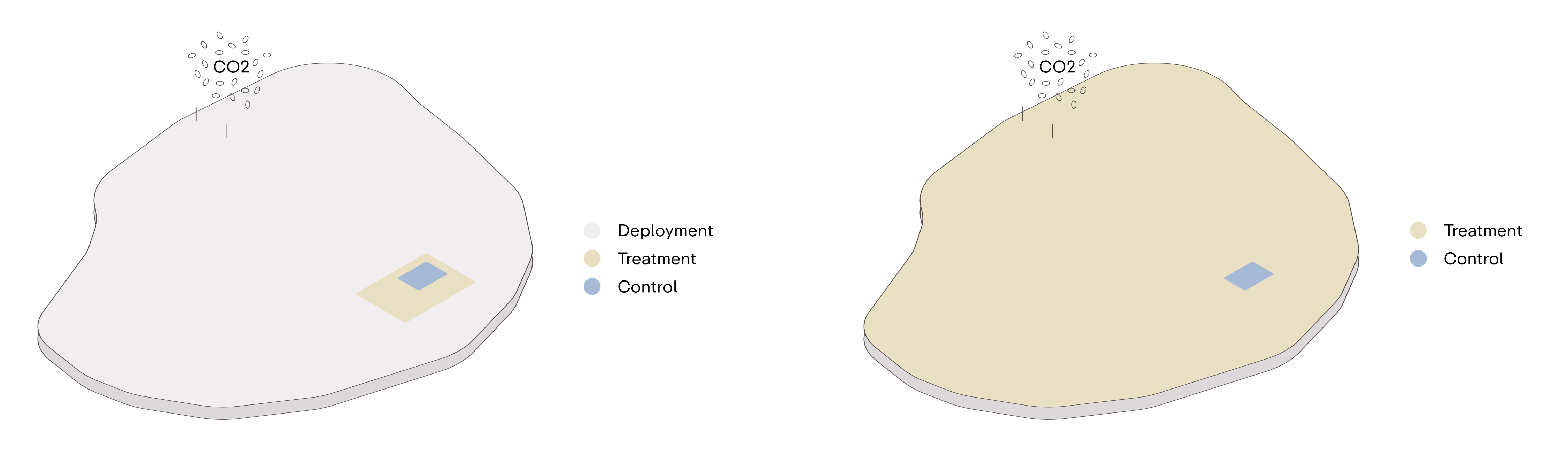
Figure 2 Schematic of in-field monitoring approaches, illustrating the relative size of the control, treatment, and deployment plots in the 3- and 2-plot approaches.
12.4.1.1
2-plot Approach Framework
The 2-plot approach for quantifying CO2 removals via OSEM calls for the designation of the Project site into one of two categories:
- Control Plot - An area utilized to assess the Project counterfactual, demonstrating representative passive CO₂ removal under baseline conditions
- Treatment Plot - An area encompassing CO₂ removal activities undertaken by the Project Proponent, which will be used to quantify creditable removals resulting from Project activities
12.4.1.2
3-plot Approach Framework
The 3-plot approach allows for collection of high-resolution data from OSEM Projects on a smaller scale, while enabling lower-resolution monitoring across the remainder of the Project site. In this setup, the Project site is divided into three distinct sections: control, treatment, and deployment areas, defined as follows:
- Control: An area utilized to assess the Project counterfactual, demonstrating representative passive CO₂ removal under baseline conditions.
- Treatment: A densely monitored area where CO2 removal from the application of mineral feedstock is measured in detail, providing high-resolution data on carbon mineralization performance.
- Deployment: A less densely monitored area where CO2 removal from mineral feedstock application is tracked at a broader scale.
Unless specified otherwise, data collected in each of these areas will be used to quantify CO2 removal specifically within that area (e.g., samples from the deployment area are used to quantify removals in that area). In some cases, data from the treatment area may be extrapolated to the deployment area to quantify metrics that may not be quantifiable at the scale of the deployment area, for example solid and aqueous samples for Projects where Quantification Option 2 has been employed.
12.4.1.3
Control Plot (2-plot or 3-plot)
The purpose of the control plot(s) is to quantify the baseline carbon removal or emissions that would occur naturally in the absence of Project intervention. The control plot area must represent at least 2.5% of the total project area. The control plot should remain untreated over the Project Reporting Period, reflecting baseline conditions without any additional interventions by the Project Proponent.
12.4.1.4
Treatment Plot (2-plot or 3-plot)
The treatment plot encompasses the Project site where rock or mineral feedstock is treated for the purpose of carbon removal. Typically, this plot covers 97.5% (2-plot) or 2.5% (3-plot) of the defined Project site and is monitored according to the Project’s monitoring and sampling plans. The treatment plot encompasses the Project site on which rock or mineral feedstock is applied or treated for the purpose of carbon removal. The treatment area will be subject to monitoring as prescribed by the Project monitoring and sampling plans.
12.4.1.5
Deployment Plot (3-plot)
The deployment area encompasses the remaining Project site not included within the control or treatment plots and typically represents 95% of the total Project site.
12.4.1.6
Designating Control and/or Treatment Areas
The Project Proponent must designate one or more control plot areas that are representative of the Project’s treatment plot/deployment area. Project Proponent should assess the representativeness of control plots when designating areas within the Project deployment. Such assessments should consider aspects including, but not limited to, climatic conditions (such as temperature, annual precipitation rate, precipitation pH), storage conditions (such as porewater pH), hydrology, lithology and the chemical properties of alkaline feedstocks (e.g., mineral type and abundance and particle size) within the Project site. Hydrological assessments are especially important for plots located on a TSF, as aqueous transport paths and exported fluids need to be assessed for accurate quantification of potential losses/reversals.
All data used to determine the representativeness of control, treatment and deployment (in 3-plot models) plots must be documented in the PDD. Where public or partner data is unavailable, a detailed characterization of the alkaline feedstocks (e.g., mineral surveys) must be performed, following the requirements in the Rock and Mineral Feedstock Characterization Module 1.0. Control plots should represent both the central tendencies and variance of relevant continuous variables .
Clear boundaries of all plots, including GPS coordinates and deployment maps, must be provided in the PDD. The use of buffer zones at plot boundaries is required to avoid cross-contamination between treatment and control plots. Where buffer zones are not able to be implemented, Project Proponents should engage with Isometric and provide clear justification to the omission of buffer zones within the PDD.
The control plot must be maintained under business-as-usual operational practices, and should be utilized to measure and monitor counterfactual baseline weathering rates over the Project Reporting Period (RP). Table 7 outlines minimal area designations required for Projects utilizing 2- or 3-plot models under this Protocol.
12.4.2
Sampling Requirements
Under this Protocol’s Crediting frameworks, a combination of solid, aqueous and gaseous phase measurements are required to demonstrate durable carbon removals via OSEM, (see Section 10.4). Sampling plans should be designed to accurately assess net CO₂ removal, efficiency of removal activities, leakage/reversals and environmental safeguarding.
Sampling depth for solid and aqueous sampling within a Project site must be stated and justified in the PDD. The justification should include evidence that the depth range captures the relevant geochemical processes.
The following sampling details must be reported and justified in the PDD:
- Sampling Frequency and Timing
- Sampling Locations
- Sample Types and Properties
- Sample Size and Volume
- Analytical Techniques (including minimum detection limits)
- Data Quality and Control
The number of samples needed should be designated on a Project by Project basis, depending on the size of the Project site and heterogeneity of the utilized alkaline feedstock.
For aqueous samples, such as pore water, groundwater, surface water and leachate, which are used to quantify CO2 removals and undertake environmental monitoring, Project Proponents must include and document measurements in line with the requirements outlined in Section 12.5 (refer to Table 8).
Sampling techniques, designs, methodologies and equipment must be documented in the PDD, and any changes to sampling procedures must be approved by Isometric.
12.4.3
Statistical Considerations for Sampling and Crediting
This Section provides guidance on determining the number of control and treatment samples needed to demonstrate statistical significance under this Protocol.
12.4.3.1
Statistical Guide for Sampling
The sampling density utilized to quantify carbon removal and environmental monitoring must be determined based on the variability observed during the feedstock characterization. In areas with low variability, the number of sampling points may be reduced while still ensuring that the data remains statistically representative. However, in zones exhibiting high measurement variability, the number of sampling locations must be increased proportionally to accurately capture spatial differences in feedstock composition. The total number of sampling points should be sufficient to cover the entire Project site. In some instances, repositioning sampling equipment during the monitoring period is allowed to achieve broader spatial coverage, ensuring that measurements reflect the full scope of the carbon removal processes across the treatment and control plots.
Equation 20 provides an estimate of the minimum number of samples needed to achieve statistical significance, assuming normally distributed data:
(Equation 20)
Where:
- N is the number of samples needed for statistical significance
- σ is the standard deviation of parameters been measured, such as base cation concentration (or other geochemical signal of mineralization) over an area of interest
- is the the Z-score associated with the significant level of interest (1.96 for two-tailed, 1.645 for one-tailed)
- the minimal detectable changes which the project aims to statistically validate. This could be changes in baseline cation concentration or other geochemical signals of mineralization from the beginning to the end of the Reporting Period. This value helps determine the sensitivity of the study — the smaller the value of , the larger the sample size required to statistically detect such a change.
With a rearrangement of the formula based on the mean of the quantifying measurement, the Project Proponent can derive the minimum number of samples needed to achieve statistical significance. It is recommended that the Project Proponent uses a conservative estimate for Smin when using this equation to determine the number of samples needed for statistical significance.
12.5
Measurement Requirements for Removal Quantification
This Section outlines the key measurements that will be required by a Project Proponent to demonstrate removals, emissions and quantify potential reversals. Project Proponents have two options for quantification and validation of OSEM removals (as outlined in Section 10.5.1.1):
Quantification Option 1 - Quantification with solid- and aqueous-phase geochemical measurements and local validation by gas-flux measurements
Quantification Option 2 - Quantification with gas-flux measurements and local validation by solid- and aqueous-phase geochemical measurements.
Local validation checks need only be collected in the control and 2.5% of the Project site (or the treatment plot in the 3-plot approach).
Under this Protocol, the following measurement types are required for removal quantification and validation:
- Gaseous Phase Measurements: Measurement of gas flux and composition can be used to quantify . Direct quantification of the gas phase represents the gross CO2e stored, without adjustments for any losses from the removal process; these losses should be accounted for during monitoring and verification to ensure accurate net storage values.
- Solution/Aqueous Measurements: Characterization of aqueous phases is required to quantify and calculate parameters such as and , especially when gas-phase measurement is the primary method for quantification. This characterization is also essential when aqueous and solid phases are the primary storage mechanisms for . Additionally, these measurements are required to account for any CO2e losses and gains within the aqueous phase.
- Physical/Solid phase Measurements: Characterization of solid phases are required to quantify and calculate parameters such as and in mineral phase, especially when gas-phase measurement is the primary method for quantification. This characterization is also essential when aqueous and mineral phases are the primary storage mechanisms of .
Table 8 summarizes the required and recommended measurements for quantification and validation. Solid phase measurement techniques should follow the guidance outlined within Isometric Rock and Mineral Feedstock characterization. The measurement requirements and recommendations outlined in Table 8 should be applied to control, treatment and deployment plots (where applicable) by the Project Proponent.
Where a Project Proponent deviates from the required measurement techniques, or has developed a novel technique or procedure that satisfies the purpose of a required measurement, a Project may still be considered for Crediting under this Protocol. In such an instance, the Project Proponent is required to submit the alternative method to Isometric for assessment and approval, prior to Credit issuance or removal validation within a Reporting Period (RP). Where alternative measurements have been used by a Project Proponent, the methodology and rationale for use must be outlined clearly in the PDD upon submission to Isometric and the Project VVB.
Table 8. Measurement requirement and recommendation summary
| Phase | Measurements | Required or Recommended | Reason for measurements |
|---|---|---|---|
| Gaseous Phase Measurements | CO2 fluxes via e.g., eddy-covariance and dynamic-closed chamber | Quantification Option 1 - Required Quantification Option 2 - Required | Validation and quantification of CO2 fluxes which encompass both flow rate and amount of CO2 in a given volume of air or gas mixture allows:
|
| Non-CO2 Gas composition | Quantification Option 1 - Recommended Quantification Option 2 - Recommended | Analyze overall composition of gas stream (e.g., presence of other gasses like oxygen or nitrogen) as well as measuring trace gasses. | |
| Gas pressure and temperature | Quantification Option 1 - Recommended Quantification Option 2 - Recommended | Temperature affects the solubility of CO2 in solution; Partial pressure of gas influences reaction kinetics; both should be measured, both temporally and spatially for Project related activities. | |
| Solution/Aqueous Measurements | Mineral saturation | Required | Composition of any fluids (leachate/groundwater) within the storage sites. This should be collected via a monitoring well or “leachate collection pipeline” within the Project site. Solution/aqueous measurements provide insight into the interactions between CO₂, minerals and the aqueous solution, allowing:
|
| Depth to fluid | Required | ||
| Temperature | Recommended | ||
| pH | Required | ||
| Alkalinity | Required | ||
| Electrical conductivity | Recommended | ||
| Dissolved Inorganic Carbon (DIC) | Required | ||
| pCO2 | Recommended | ||
Major cations (e.g., Mg2+, Ca2+, Na+, K+, Fe2+/Fe3+, Mn2+) | Required | ||
Major anions (e.g., HCO3-, Cl-, SO42-, NO3-) | Required | ||
| Total dissolved solids | Recommended | ||
| OPR (Oxidation-Reduction Potential) | Recommended | ||
| Solid Phase Measurements | Mass of feedstock | Required | Solid measurements can be used to quantify mineralized CO2 . Solid phase measurements also allows:
|
| Total inorganic carbon (TIC) | Required | ||
| Mineral composition | Required | ||
| Major and trace elements | Required | ||
| Particle size distribution | Quantification Option 1 - Required Quantification Option 2 - Recommended | ||
| Surface area | Quantification Option 1 - Required Quantification Option 2 - Recommended | ||
| Porosity | Quantification Option 1 - Required Quantification Option 2 - Recommended | ||
| Morphology and microstructure | Recommended | ||
| Temperature & pressure | Recommended |
Note: Where a parameter is required or recommended for a specific Quantification Option this has been outlined in bold text within this table.
Where applicable, analytical methods must be cross-referenced with an appropriate standard (e.g., ISO, EN, BSI, ASTM, EPA) or standard operating procedure (SOP). Where a Project utilizes a non-standardized methodology or SOP for the determination of a listed parameter, the Project Proponent is required to outline the relevant method within the PDD submitted to the Validation and Verification Bodies (VVB).
12.5.1
Gas Phase Measurements
Where a Project Proponent utilizes gas phase measurements for quantification or validation of net Project removals, a comprehensive monitoring plan is required. Removals may be quantified via quantification option 2 (or verified in quantification option 1, see Section 12.5) via CO2 flux measurements collected using eddy-covariance and dynamic-closed chambers.
Where a Project Proponent utilizes solid and aqueous phase measurements to quantify net removals, Project Proponents must use gas phase monitoring to validate removals (Quantification Option 1). Project Proponents are not required to quantify gas composition, pressure and temperature, although these measurements are recommended for all Projects.
If the Project location facility (e.g., alkaline waste facility or TSF) does not have a liner (such as a geo-membrane) the Project Proponent is required to measure gas compositions and undertake a biological assessment of the underlying material to determine the potential influence on gas flux measurements. This should be carried out within the control and deployment plots to account for variations across the Project site.
Gas phase measurements are required to be carried out at day and night, in order to account for diurnal cycles, for both quantification option 1 and 2.
Gas phase measurement plans should be clearly outlined in the PDD. The installation methodologies, device types and sampling frequency must be outlined in the PDD. Project Proponents should ensure that the same device types and procedures are used for the RP to maintain consistency in data collection. Any changes in device type or sampling methods must be approved by Isometric.
12.5.2
Aqueous Phase (Porewater) Measurements and Downstream Losses
Projects must directly measure porewater as part of a comprehensive monitoring plan. Porewater must be sampled at a frequency that is appropriate considering the local hydrology, precipitation, and temporal evolution of dissolved ions. The water sampling plan must be described and justified in the PDD. The sampling plan should additionally consider events that significantly impact moisture content, such as heavy rainfall and extreme weather events; this will be determined on a Project- and event-specific basis. All fluid sampling devices (porewater, groundwater, and process water) must be installed and maintained consistently throughout the Project. The installation methodology, device types and sampling frequency must be outlined in the PDD. Project Proponents should ensure that the same device types and procedures are used for the Project duration to maintain consistency in data collection. Any variations in device type or sampling methods must be approved by Isometric.
In some instances, it may be appropriate to implement groundwater or mine process water monitoring as part of a comprehensive monitoring plan for either removal quantification or estimation of downstream losses. In such instances, the Project Proponent must describe the monitoring plan in the PDD, including frequency, specific analyses, and how these measurements will be used as part of carbon accounting.
12.5.2.1
Aqueous Measurement Requirements
Project Proponents utilizing aqueous measurements must complete a full suite of fluid characterization measurements. A comprehensive monitoring plan of aqueous phase samples must be designed in line with Section 12.4, Table 8 and Appendix 3, to ensure accurate tracking of CO2e stored, alkalinity flux and potential environmental impacts (See Section 8).
Analytical Methods and Standards
All water samples should be analyzed using standardized methods suitable for high-accuracy environmental monitoring. Common techniques include:
- Cation and anion analysis - Ion Chromatography (IC), ICP-MS and/or ICP-MS
- Measurement of at least two carbonate system parameters
Carbonic acid system measurements may include carbonate alkalinity titration to the CO2 equivalence point, pH, DIC and/or pCO2, followed by calculating the concentration of bicarbonate using the 2-for-6 method. Calibration and maintenance records for all instruments must be kept up-to-date and made available for audit, ensuring data accuracy and consistency over the Project’s lifetime.
12.5.2.2
Downstream Losses
Aqueous phase CO2 storage must also consider the potential for downstream reversal, including outgassing associated with carbonate system re-equilibration in streams, rivers, or the ocean. Project Proponents must identify potential flow paths for aqueous phases and the final storage reservoir, whether that is located at the Project site or eventually transported to the ocean. A reversal risk monitoring plan must include an assessment of flow paths within and outside the defined Project boundaries for a deployment.
Geochemical modeling of aqueous phase storage and interactions with the wider environment may be used to quantify downstream losses associated with carbonate system equilibration. It is recommended that such models consider:
- pH of the reservoir and the alkaline fluid
- Carbonate saturation state
- Discharge & recharge rate
- Groundwater flow rate
- Hydraulic conductivity & gradient
Further guidance on utilizing models to quantify downstream aqueous losses can be found in Section 12.7 of this Protocol.
12.5.2.3
Watershed/Rivers
CO2 stored in aqueous phase represents a stable and durable mechanism for CO2 removal, as dissolved bicarbonate and carbonate ions can persist over long periods, especially in deep groundwater or marine systems with long alkalinity residence times. However, CO2 degassing may occur during the downstream transport of captured CO2 to the ocean, resulting in reversal/leakage of stored carbon. This may occur through the following processes when exported alkalinity is transported out of the Project site:
- Re-equilibration and outgassing in groundwater and/or river networks
- Calcium or Magnesium carbonate precipitation in groundwater and/or river networks
Leakage as a result of re-equilibration of the carbonic acid system occurs following the CO2 dissolution in aqueous solution reactions listed in Equations 4-6 in Section 7.1.2.
Speciation of dissolved inorganic carbon (DIC) is pH-dependent, and mixing of two fluid parcels can result in outgassing from re-equilibration of these dissolved species.
Ca2+, Mg2+ and/or Fe2+ carbonate forms through the reaction shown in Equation 21:
(Equation 21)
Where:
- M2+ represents a divalent metal cation
Carbonate formation in river systems should be quantified separately from carbonate formation in feedstocks as rivers represent an open system where dissolved CO₂ may degas across the water surface. Any carbonate formation will result in a loss of 50% of the corresponding exported alkalinity.
The fate of exported alkalinity during river transport remains poorly constrained. To account for potential downstream losses, Project Proponents seeking Credits for aqueous phases alkalinity are required to model expected losses based on expected feedstock dissolution rate, watershed chemistry and river basin chemistry. These models should be based on publicly available historic watershed and river network data. Several recent publications have discussed modeling approaches that combine baseline river geochemical data, equilibrium modeling of water chemistry and scenarios of OSEM in ultramafic tailings 64 65. For example, to characterize Mg-carbonate precipitation, 66 demonstrated that carbonate saturation state (SIm) may be calculated as follows for magnesite:
(Equation 22)
With:
- is the solubility product of magnesite:
Where:
- is the measured solution concentration (activities) of the ions
- is the concentration (activity) of the ion at saturation
When > 0, a river is considered supersaturated
Geochemical models of riverine losses must include the following parameters in both the full river network through which dissolved weathering products will be transported and the groundwater that drains from the deployment field to the river network:
- Baseline SI of Ca, Mg and Fe carbonate
- pH
- EC
- pCO₂
- Temperature
- Alkalinity
Project Proponents are required to submit a detailed description of their modeling approach, including the model used, the river/watershed data, measurements used in model construction and the source of that data, in the PDD.
12.5.2.4
Ocean
For OSEM Projects, such as those using ultramafic mine tailings, the ultimate storage reservoir for CO₂ sequestered as alkalinity may include bicarbonate (HCO₃⁻) and carbonate (CO₃²⁻) ions in the ocean. However, when the generated alkalinity reaches marine environments, similar processes to those observed in river systems can lead to reductions in the overall amount of CO₂ effectively removed. These reduction mechanisms are important to consider for accurate quantification of net carbon removal:
Carbonate Precipitation
Once alkalinity enters the ocean, carbonate precipitation can occur, reducing the amount of DIC stored in bicarbonate form. This precipitation process can happen either abiotically or through biological mediation, particularly in surface waters where specific biogeochemical conditions support calcifying organisms. Calcium and magnesium carbonate precipitation reduces the storage efficiency of CO₂, as the bicarbonate reservoir becomes partly converted into solid mineral phases that do not persist as dissolved forms of carbon. Because of the small volumes of export anticipated from OSEM Projects, it is unlikely that exported alkalinity will significantly impact the carbonate saturation of the ocean basin; thus, carbonate precipitation is not considered further here.
Re-Equilibration of Dissolved Inorganic Carbon (DIC)
Upon entering the ocean, the newly introduced alkalinity may undergo re-equilibration due to changes in pH, temperature, and salinity, which impact the balance of bicarbonate, carbonate, and dissolved CO₂ species. Typically, ocean waters have a higher pH than inland waterways, resulting in a shift toward greater concentrations of carbonate ions (CO₃²⁻) within the DIC pool. This shift in speciation slightly reduces the CO₂ removal efficiency as it increases the proportion of carbonate ions relative to bicarbonate ions, leading to a reduction in the total CO₂ stored in the ocean as a result of the mineralization process.
While these processes introduce a level of reduction in total CO₂ storage, it is necessary to account for these factors upfront, given that the timescales and spatial scales over which CO₂ reaches the ocean are too extensive for direct monitoring over a Reporting Period. Depending on the Project location and the hydrological system, the time it may take for removed CO₂ to reach marine systems could span decades, with marine dilution further dispersing the generated alkalinity.
Quantifying Carbon Losses
Projects with removals that include exported DIC must consider losses that result from re-equilibration upon entering the ocean. A Project Proponent can account for these potential losses using either applicable scientific literature or thermodynamic modeling of the carbonate system. The equation for uptake efficiency developed by Renforth and Henderson (2017)67 quantifies the change in total DIC as a function of the change in total alkalinity upon reaching the ocean, providing a tool for estimating these impacts. In such instances a Project Proponent would be required to identify which ocean basin their deployment site drains into, based on river catchment flows. Oceanographic conditions identified from publicly available locationally-specific time-series data, such as the NOAA climate indices list, OceanSODA-ETHZ, or equivalent. This data should be used to quantify uptake efficiency and to determine the appropriate deduction for marine loss. These variables may also be calculated using softwares such as CO2SYS or PyCO2SYS. The Project Proponent must include a detailed description of how oceanic losses are determined in the PDD.
12.5.3
Solid Phase Measurements
Project Proponents are required to undertake solid phase measurements as part of a comprehensive monitoring plan. Solid phase measurements must be used to quantify or validate net Project removals, especially when gas phase measurements are the core measurements used to quantify removal (Quantification Option 2). A detailed monitoring plan is required for solid phase sampling within control, treatment and deployment (3-plot approach) plots within a Project site . Solid phase measurements may be conducted through periodic sampling and analysis of the solid matrix to evaluate inorganic carbon content increase, mineralogical transformations, and other relevant indicators of net carbon removal. Project Proponents must specify the sampling strategy, including frequency, depth, and location, in accordance with the characteristics of the Project site and targeted solid materials.
The sampling plan should be clearly outlined in the Project Design Document (PDD) and justified based on the project’s geological and mineralogical context. Sampling should account for any events that could influence the solid phase, such as mining operations, waste deposition activities, or environmental events that might impact carbon removal rates. Sample preparation and analysis methods must also be undertaken in line with Isometric’s Rock and Mineral Feedstock Characterization Module 1.0. Project Proponents are required to clearly document the type of analyses (e.g., mineral carbonation assessment, carbon content determination) and laboratory techniques utilized for all solid phase measurements.
Where the presence of other media (such as soil and peats) may impact carbon storage estimates, Project Proponents are required to include a biological and chemical assessment of these materials, both in the control and deployment plots. Measurement and monitoring plans are required to be designed to account for heterogeneity in solid-phase measurements across the Project site. Specific guidance for monitoring mine Tailings are outlined in Section 12.6.3 of this Protocol.
All solid sampling devices and protocols must be consistent throughout the Project to ensure reliable data collection. Any modifications to device types or analytical procedures must be approved by Isometric.
12.5.3.1
Non-Carbonate Mineral Formation
Project Proponents are recommended to measure non-carbonate mineral formation during OSEM processes. Secondary minerals that may form as a result of the reaction between CO₂, water and the alkaline materials include clays and hydroxides, such as Layered Double Hydroxide (LDH) group minerals which could enhance the reactivity of the system and promote further CO₂ uptake. Secondary hydroxides and clays should be investigated through mineral identification and quantification analysis such as X-ray diffraction (XRD), short-wave infrared technologies (SWIR), hyperspectral imaging (HSI) that are adopted commonly in industries such as mining exploration. Further mineralogical and chemical analysis, such as scanning electron microscopy coupled with energy dispersive spectroscopy (SEM-EDS), are recommended for additional quantification. Secondary clay formations are difficult to quantify using widely accessible techniques at this time, and will not be counted towards CDR quantification.
While these mineral formation dynamics are central to developing a mechanistic understanding of OSEM, explicit quantification of these mineral phases is not required. Any reversals that result from secondary mineral phase formation within the Project site during Project activities will otherwise be accounted for in the quantification measurements outlined in this Protocol.
12.5.3.2
Quantification of Maximum CDR Potential from Feedstock Application
Theoretical maximum removal potential of a feedstock material, based on an adjusted version of the Steinour Equation (see Section 3.4.1.1 of the Isometric Rock and Mineral Feedstock Characterization Module 1.0) is required for all Projects.
Elemental abundance data should be produced according to methods prescribed in the Rock and Mineral Feedstock Characterization Module 1.0. The calculated CDR potential represents the upper limit of creditable removals for a single batch of feedstock as defined in the Rock and Mineral Feedstock Characterization Module 1.0. Project Proponents are required to report the CDR potential of each batch of feedstock used pursuant to Project activities in the PDD.
The use of an alternative calculation of a feedstock's maximum removal potential may be utilized by a Project Proponent. The suitability of alternative methods will be assessed on a Project by Project basis. Project Proponents should engage with Isometric to determine the suitability of alternative quantification methods.
12.6
Monitoring Long-term Stability Requirements
Storage monitoring should focus on ensuring the long-term stability and integrity of the stored carbon within the Project deployment/storage location. Effective storage monitoring involves a combination of geochemical, geophysical, and environmental techniques to track the stability of the sequestered carbon, detection of potential leakage, and monitoring of environmental impacts, directly or indirectly related to the Project activity. Section 4 of the Carbonated Materials Storage and Monitoring Module list all the monitoring requirements for carbonate materials within a suitable storage facility. This section outlines the monitoring approach that Project Proponents must take in Crediting Projects.
12.6.1
Reversals
Project Proponents are required to implement measures, from Project conception, to prevent reversals and leakage. If any reversal or leakage, as highlighted in Section 12.2, is detected from the storage site, or there is greater than 5% deviations from utilized models, the Project Proponent must undertake corrective measures as set out in the Project monitoring plan. Where reversals are confirmed through direct measurements or ongoing monitoring, a Project Proponent may be required to complete additional monitoring or measurements to fully quantify reversals . Changes to monitoring plans due to the identification of Project reversals will be assessed and approved by Isometric on a Project by Project basis. Where leakage is potentially identified, a Project Proponent is required to notify Isometric within 30 days.
12.6.2
Storage Reversal Risk Monitoring and Quantification
For OSEM Projects where interactions with the surrounding environment are more dynamic and less contained than closed system processes, a comprehensive reversal risk assessment must be conducted. When developing a reversal risk monitoring plan, Project Proponents are required to follow the criteria outlined in Sections 4.1.2 and 6 of the Carbonated Materials Storage and Monitoring Module 1.0.
Refer to Carbonated Materials Storage and Monitoring Module for details.
The following is an overview of reversal risk storage monitoring under this Protocol:
- Geochemical Monitoring:
- Carbonate mineral stability: Regularly monitor the stability of carbonate minerals formed in the open system. This involves periodic sampling of solid material and analyzing for signs of mineral dissolution or changes in mineral phases that could indicate potential CO2 release.
- Pore-water fluid chemistry: Regularly monitor the chemical composition of any leachate generated by the system, focusing on pH, alkalinity, and dissolved carbon species (carbonate, bicarbonate, CO2).
- Environmental Monitoring:
- Groundwater and surface water quality: regularly sample and analyze groundwater and surface water around the site for changes in pH, dissolved CO2, and carbonate ion concentrations, which could indicate leaching or carbonate dissolution. Heavy metal and sulfur/sulfate measurements are recommended to assess the potential release into the wider environment.
- Regularly assess ecosystem health around the storage area (where applicable)which could indicate alterations in soil chemistry, possibly due to CO2 release or other environmental impacts such as AMD. Indicators for impacts to ecosystem health may include, but are not limited to, changes in biodiversity, decreases in population density or plant productivity of local species.
Note: Project Proponents are recommended to reference the IUCN red list, or other reputable endangered species list to monitor changes in biodiversity in their project region as potential indicators for environmental monitoring
- Geophysical Monitoring:
- Surface and subsurface stability: Geophysical methods, such as ground-penetrating radar and seismic survey may be used to monitor for erosion, subsidence or other physical changes in the site that could lead to exposure of stored carbon or instability storage structures (such as a TSF)
- Long-term Monitoring and data analysis
- Establish long-term monitoring programmes that track the stability of the stored carbon over extended periods, accounting for seasonal and interannual variations in environmental conditions.
12.6.3
Tailings Monitoring
This Section outlines specific monitoring criteria required when Projects are undertaken using mine tailings within a mining operations tailings storage facility (TSF).
12.6.3.1
Sampling of Tailings
Sampling of utilized mine tailings is essential for monitoring OSEM Project activities and within the tailings storage facility (TSF). The physical and chemical characteristics of tailings evolve over time, influenced by factors such as addition of new tailings, weathering, particle size distribution (PSD), mineral type and abundance and exposure to environmental conditions. As such, regular sampling to account for heterogeneity in tailings is required to monitor CO₂ removal and storage progress throughout the Project.
Key considerations for sampling tailings:
The Project must undertake sampling at time intervals and density that capture the progression of carbon mineralization and heterogeneity within the TSF. Initial baseline sampling should be taken at the start of the Project, followed by repeated sampling campaigns at regular time intervals (e.g., every 6 to 12 months) to track mineralization depth and the degree of carbonation.
- Sample Locations: Sampling plan and sampling locations (e.g., grid sampling) should be described and justified in the PDD, and designed to capture inherent variability of the project site.
- Sampling Depth: Depending on tailings properties and depth, sampling may require specialized equipment such as augers or rotary corers capable of retrieving undisturbed samples. Sampling depth will be determined on a Project by Project basis. Samples should be preserved to avoid carbonation or contamination during transport to the laboratory for analysis.
Details on the coring frequency, depth, location and equipment must be included in the PDD upon submission to Isometric and the Project VVB.
12.6.3.2
Accounting for New Tailings Depositions
Where Projects are undertaken on an active TSF and newly generated tailings are added to the TSF over the course of the Project, freshly deposited layers must also be accounted for in the monitoring and verification of carbon removal and emissions estimations. New tailings may have different physical and chemical properties, which can influence their reactivity and capacity for CO₂ removal.
Key requirements for managing and monitoring new tailings include:
- Tracking Tailings Deposition: Accurate records of the quantity, composition and deposition date of new tailings added to the TSF must be maintained. This includes identifying specific areas where new tailings are deposited, as these areas may require distinct monitoring strategies.
- New Tailings Characterization: As new tailings are deposited, they should be sampled for initial characterization, including particle size distribution, mineralogical composition and chemical properties relevant to carbonation potential. Baseline samples should be taken immediately after deposition to monitor how these tailings contribute to carbon removal within a Project site over a Reporting Period.
- Incorporation into Monitoring Program: New tailings should be incorporated into the ongoing sampling and monitoring program. If new tailings are deposited in a specific zone of the TSF, this area must be integrated into the regular grid of coring sites, where the deposited tailings fall within the defined deployment areas. The timing of sampling in these areas may need adjustment to reflect the time elapsed since deposition and the expected modeled/measured rate of mineralization over a Reporting Period.
- Depth Considerations: As new tailings are added on top of existing layers, sampling should continue to capture the full vertical profile, including both old and newly deposited tailings. This allows for accurate tracking of carbon removal throughout the depth of the TSF.
- Reporting Requirements: The Project must report on the volume and characteristics of newly deposited tailings and integrate these data into the overall carbon balance, where the addition of new tailings impact Project removals or emissions. Regular reporting updates on the removal performance of newly added tailings, following the Project monitoring plan, are necessary for accurate accounting of CO₂ removal over a Reporting Period. Any variations in deposition patterns, such as changes in tailings mineralogy or significant shifts in deposition rates, should be documented and reported, as they may affect the overall removal potential.
12.7
Modeling Requirements
There may be instances throughout a Project where models are appropriate for both quantification and reversal monitoring that cannot be readily observed. Additionally, geochemical models are useful tools for estimating the carbon removal baseline and Project scenarios during a Reporting Period. At this early stage of carbon removals, geochemical models are not sufficient for Crediting and should only be used as a guide for Project activities. It is anticipated that the role of geochemical models in quantification of carbon removal projects will evolve in the coming years, and future updates in this Protocol will reflect this evolving consensus.
We recommend that any models used or developed alongside Project activities meet the following criteria:
- Are publicly available
- Validated against a recognized reactive transport model benchmark
- Effective in modeling CO2 uptake in crushed rock of variable saturation as demonstrated in peer-reviewed publications e.g., MIN3P, PHREEQC (Version 3), GWB (Geochemist's Workbench)
- Able to reproduce baseline and/or Project measurements at a specific sites
- Built based on baseline data for the case of a baseline model and Project data for the case of Project model
- Assessed by an independent third party
- Validated against a dataset that was not used for calibration. In the case where publicly available, peer-reviewed experimental datasets exist for a specific Project, they may be used for model validation
For models used to simulate geochemical reactions, the following are essential components and considerations to include in developed models:
- Chemical characterization of the feedstock materials: mineral type and abundance and reactivity
- Water chemistry: solute concentrations that might influence mineral dissolution and precipitation reactions
- CO2 source and transport: both gas phase interaction (injection vs dispersion of CO2), transport mechanisms, porosity and permeability are important parameters to be included in the input
- Kinetic rates: input detailed reaction kinetics, temperature and pressure conditions
- Thermodynamic database: use a database with equilibrium constants and activity coefficients from peer-reviewed literature for specific Project context
- Modeling scenarios: model baseline vs Project scenarios, conduct sensitivity analysis
- Scale of modeling: clearly state and confirm spatial variability and scale of the model
- Validation and calibration: Use laboratory or field data for calibration and establish methods for model validation against independent datasets
For models to simulate reversal risk, the following are recommended components and considerations to include in developed models:
- Environment trigger analysis: the impact of acidic conditions on solubility and stability of carbonate minerals should be evaluated; along with risk of water logging
- Long-term geochemical process: assess the potential for secondary mineral formation that might stabilize or destabilize the primary carbonated product; examine the current and the long-term buffering capacity of the surrounding environment
- Scenario modeling: various scenarios of modeling should be conducted, specifically worst case scenario and probability risk assessment should be included
- Mitigation strategy evaluation: evaluate the mitigation strategy via modeling if a chemical process is involved
- Model validation and update: Use laboratory or field data for calibration and establish proper methods for model validation against independent dataset. Regularly update models based on new findings and new data collection.
12.8
Missing Data, Outliers and Unexplained Results
In some cases, extreme, localized heterogeneity may result in measurements or data that are missing, incomplete or out of line with expectations given the Project design or previous measurements. Similarly, disruptions to the Project site and ongoing monitoring (e.g., extreme weather events or equipment failure) may result in missing data, outliers or unexplained results. For the purposes of this Protocol, outliers are defined as data that are more than three standard deviations from the mean (or equivalent percentiles for non-normal distributions). In such instances, the Project Proponent may seek clarification on how the data should be handled. When such instances occur, the details must be remedied and reported to the VVB and Isometric as quickly as possible after identification. In such situations, and on a case-by-case basis, Isometric will work to remedy the situation in consultation with the Project Proponent and VVB.
12.9
Recordkeeping
All records associated with the characterization, design, deployment and monitoring should be kept for a minimum of 10 years after cessation of removal activities and closure of the storage location. All documentation should be submitted to relevant authorities, such as environmental regulatory bodies, as required by local permitting regulations. In instances where project ownership changes ,during or post removal activities, the Project Proponent should contact Isometric to assess the potential implication of ownership change on Removal durability and reversal risk.
12.10
Use of Existing Data Sets
Where site and feedstock characterization may have been carried out as part of permitting, or for other regulatory and compliance purposes, a Project Proponent may submit such results to meet the requirements of this Protocol. The use of such data for Crediting purposes must be approved by the Project VVB and Isometric prior to the issuance of removal Credits. If a Project Proponent intends to use pre-existing data sets in accordance with this Protocol, the data source, methodologies and data collection must be clearly outlined within the PDD to allow validation of submitted data prior to Crediting.
The use of existing data sets is contingent upon the approval of the relevant organization, or individuals, that are responsible for that data set, in instances where the data was not collected by the Project Proponent directly. It is the responsibility of the Project Proponent to ensure submitted data has been adequately checked for accuracy and that relevant permissions have been sought, and subsequently approved, prior to submission to Isometric and the Project VVB.
12.11
Projects Started Prior to this Protocol
Projects that were started prior to the publication of this Protocol may be eligible for Crediting under this Protocol on a case-by-case basis. Project Proponents seeking Credits for pre-existing deployments must justify the approach taken in these Projects in the PDD, with special attention paid to:
- Sampling plan design, particularly regarding the quantification of in-field heterogeneity
- Sample depth
- Sample pooling practices
- Any other major deviations from the current Protocol requirements
Projects started prior to the publication of this Protocol are subject to the same statistical significance requirements referred to in Section 12.4.3.1
13.0
Acknowledgements
Isometric would like to thank following contributors to this Protocol and relevant Modules:
- Greg Dipple (Arca Climate)
- Beatrice Kigodi (Arca Climate)
Isometric would like to thank following reviewers of this Protocol and relevant Modules:
- Phil Renforth (Heriot Watt University)
- Dan Su (Heriot Watt University)
- Devin Sapsford (Cardiff University)
- Bart De Baere (WSP)
- Sean Capstick (WSP)
- Julien Declercq (WSP)
- Cara Maesano (RMI)
- François de Rochette (RMI)
14.0
Definitions and Acronyms
- Reputable SourceA source that would be widely considered trustworthy based on the process undertaken (e.g., peer review) or origin of the information (e.g., government body).
Acid Mine Drainage (AMD)
Acid mine drainage (AMD), often referred to as acid rock drainage (ARD), if a term used to describe acidic ,and often metalliferous, drainage produced through the weathering of mining wastes, such as waste rock and tailings materials.
Activity
The steps of a Project Proponent’s Removal process that result in carbon fluxes. The carbon flux associated with an activity is a component of the Project Proponent’s Protocol.
Additionality
An evaluation of the likelihood that an intervention—for example, a CDR Project—causes a climate benefit above and beyond what would have happened in a no-intervention Baseline scenario.
Baseline
A set of data describing pre-intervention or control conditions to be used as a reference scenario for comparison.
Buffer Pool
A common and recognized insurance mechanism among Registries allowing Credits to be set aside (in this case by Isometric) to compensate for Reversals which may occur in the future.
Buyer
An entity that purchases Removals, often with the purpose of Retiring Credits to make a Removal claim.
CEC
Cation Exchange Capacity
Carbon Dioxide Equivalent Emissions (CO₂e)
The amount of CO₂ emissions that would cause the same integrated radiative forcing or temperature change, over a given time horizon, as an emitted amount of GHG or a mixture of GHGs. One common metric of CO₂e is the 100-year Global Warming Potential.
Carbon Dioxide Removal (CDR)
Activities that remove carbon dioxide (CO₂) from the atmosphere and store it in products or geological, terrestrial, and oceanic Reservoirs. CDR includes the enhancement of biological or geochemical sinks and direct air capture (DAC) and storage, but excludes natural CO₂ uptake not directly caused by human intervention.
Carbon Finance
Resources provided to Projects that are generating, or are expected to generate, greenhouse gas (GHG) Emission Reductions or Removals.
Carbon Flux
The amount of carbon exchanged between two or more Reservoirs over a period of time.
Conservative
Purposefully erring on the side of caution under conditions of Uncertainty by choosing input parameter values that will result in a lower net CO₂ Removal than if using the median input values. This is done to increase the likelihood that a given Removal calculation is an underestimation rather than an overestimation.
Counterfactual
A quantification of what would have happened in the absence of a particular intervention – i.e., assuming the Baseline scenario.
Cradle-to-Grave
Considering impacts at each stage of a product's life cycle, from the time natural resources are extracted from the ground and processed through each subsequent stage of manufacturing, transportation, product use, and ultimately, disposal.
Credit
A publicly visible uniquely identifiable Credit Certificate Issued by a Registry that gives the owner of the Credit the right to account for one net metric tonne of Verified CO₂e Removal. In the case of this Standard, the net tonne of CO₂e Removal comes from a Project Validated against a Certified Protocol.
Crediting Period
The period of time over which a Project Design Document is valid, and over which Removals may be Verified, resulting in Issued Credits.
DIC
Dissolved Inorganic Carbon.
Double Counting
Improperly allocating the same Removal from a Project Proponent more than once to multiple Buyers.
Durability
The amount of time carbon removed from the atmosphere by an intervention – for example, a CDR Project – is expected to reside in a given Reservoir, taking into account both physical risks and socioeconomic constructs (such as contracts) to protect the Reservoir in question.
EW
Enhanced Weathering
Embodied Emissions
Life cycle GHG emissions associated with production of materials, transportation, and construction or other processes for goods or buildings.
Emission Reductions
Lowering future GHG releases from a specific entity.
Feedstock
Raw material which is used for CO₂ Removal.
GHG Statement
A document submitted alongside Claimed Removals, where the Project's emissions, Removals and Leakages are presented in net metric tonnes of CO₂e.
Global Warming Potential
A measure of how much energy the emissions of 1 tonne of a GHG will absorb over a given period of time, relative to the emissions of 1 ton of CO₂.
Greenhouse Gas (GHG)
Those gaseous constituents of the atmosphere, both natural and anthropogenic (human-caused), that absorb and emit radiation at specific wavelengths within the spectrum of terrestrial radiation emitted by the Earth’s surface, by the atmosphere itself, and by clouds. This property causes the greenhouse effect, whereby heat is trapped in Earth’s atmosphere (CDR Primer, 2022).
GtC
Gigatonnes of carbon
ICP-MS
Inductively coupled plasma mass spectrometry.
ICP-OES
Inductively Coupled Plasma Optical Emission spectroscopy.
International Standards Organization (ISO)
A worldwide federation (NGO) of national standards bodies from more than 160 countries, one from each member country.
Issuance (of a Credit)
Credits are issued to the Credit Account of a Project Proponent with whom Isometric has a Validated Protocol after an Order for Verification and Credit Issuance services from a Buyer and once a Verified Removal has taken place.
Leakage
The increase in GHG emissions outside the geographic or temporal boundary of a Project that results from that Project's activities.
Life Cycle Analysis (LCA)
An analysis of the balance of positive and negative emissions associated with a certain process, which includes all of the flows of CO₂ and other GHGs, along with other environmental or social impacts of concern.
Materiality
An acceptable difference between reported Removals/emissions and what an auditor determines is the actual Removal/emissions.
Model
A calculation, series of calculations or simulations that use input variables in order to generate values for variables of interest that are not directly measured.
Monitoring, Reporting, and Verification (MRV)
The multi-step process to monitor the Removals and impacts of a Project, report the findings to an accredited third party, and have this third party Verify the report so that the results can be Certified.
Pathway
A collection of Removal processes that have mechanisms in common.
Project
An activity or process or group of activities or processes that alter the condition of a Baseline and leads to Removals.
Project Design Document (PDD)
The document that clearly outlines how a Project will generate rigorously quantifiable Additional, Durable, and high-quality Removals.
Project Proponent
The organization that develops and/or has overall legal ownership or control of a Removal Project.
Protocol
A document that describes how to quantitatively assess the net amount of CO₂ removed by a process. To Isometric, a Protocol is specific to a Project Proponent's process and comprised of Modules representing the Carbon Fluxes involved in the CDR process. A Protocol measures the full carbon impact of a process against the Baseline of it not occurring.
Proxy
A measurement which correlates with but is not a direct measurement of the variable of interest.
RP
Reporting Period
RTM
Reactive Transport Model
Registry
A database that holds information on Verified Removals based on Protocols. Registries Issue Credits, and track their ownership and Retirement.
Removal
The term used to represent the CO₂ taken out of the atmosphere as a result of a CDR process.
Reversal
The escape of CO₂ to the atmosphere after it has been stored, and after a Credit has been Issued. A Reversal is classified as avoidable if a Project Proponent has influence or control over it and it likely could have been averted through application of reasonable risk mitigation measures. Any other Reversals will be classified as unavoidable.
SEM-EDS
Scanning Electron Microscopy with Energy Dispersive Spectroscopy.
Sensitivity Analysis
An analysis of how much different components in a Model contribute to the overall Uncertainty.
Stakeholder
Any person or entity who can potentially affect or be affected by Isometric or an individual Project activity.
Standards (scientific)
Standard physical constants as well as standard values set forth by bodies such as the National Institute of Standards and Technology (NIST) or others.
Storage
Describes the addition of carbon dioxide removed from the atmosphere to a reservoir, which serves as its ultimate destination. This is also referred to as “sequestration”.
Tailings Storage Facility (TSF)
Tailings storage facility (TSF) refers to a storage facility within which fine mining wastes (Tailings), that are produced as a by-product following the processing of mined ore, are stored.
Uncertainty
A lack of knowledge of the exact amount of CO₂ removed by a particular process, Uncertainty may be quantified using probability distributions, confidence intervals, or variance estimates.
Validation
A systematic and independent process for evaluating the reasonableness of the assumptions, limitations and methods that support a Project and assessing whether the Project conforms to the criteria set forth in the Isometric Standard and the Protocol by which the Project is governed. Validation must be completed by an Isometric approved third-party (VVB).
Validation and Verification Bodies (VVBs)
Third-party auditing organizations that are experts in their sector and used to determine if a Project conforms to the rules, regulations, and standards set out by a governing body. A VVB must be approved by Isometric prior to conducting validation and verification.
Verification
A process for evaluating and confirming the net Removals for a Project, using data and information collected from the Project and assessing conformity with the criteria set forth in the Isometric Standard and the Protocol by which it is governed. Verification must be completed by an Isometric approved third-party (VVB).
15.0
Appendix 1: Analytical Methods
Refer to the Rock and Mineral Feedstock Characterization Module v1.0.
16.0
Appendix 2: Site Characterization Requirements
This appendix has been adapted from Appendix 1 of the Isometric Carbonated Material Storage and Monitoring module. This Appendix should be utilized in line with Section 2 of the aforementioned module.
| Method | Parameter | Purpose | Required or Recommended | Frequency | Evidence |
|---|---|---|---|---|---|
| Geological mapping | Lithologic strength | Define surrounding lithology | Required | Once (pre crediting) | Direct/Literature |
| Porosity | Required | Direct/Literature | |||
| Permeability | Required | Direct/Literature | |||
| Hydraulic properties | Required | Direct/Literature | |||
| Likelihood and magnitude of seismic activity | Required | Literature | |||
| Geotechnical analysis of underlying strata | Geophysical measurements | Ensure sufficient strength | Recommended | Once (pre crediting) | Direct |
| Topographic survey | Storage site depth | Determine storage capacity | Recommended | Pre crediting, followed by every 5 years or prior to a new crediting period (whichever is shorter) | Direct |
| Storage site size | Recommended | Direct | |||
| Groundwater properties | Carbonate saturation | Determine likelihood of reversal from groundwater interactions | Required | Once (pre crediting) and if not actively monitored every 5 years or prior to a new crediting period (whichever is shorter) | Direct |
| Ionic concentration | Required | Once (pre crediting) and if not actively monitored every 5 years or prior to a new crediting period(whichever is shorter) | Direct | ||
| pH | Required | Once (pre crediting) and if not actively monitored every 5 years or prior to a new crediting period(whichever is shorter) | Direct | ||
| Alkalinity or DIC | Required | Defined on a Project by Project basis | Direct | ||
| Organic ligands/microbial communities | Recommended for sites located on mines Required for projects where gas-flux measurements are the main quantification measurement | Once (pre crediting) and if not actively monitored every 5 years or prior to a new crediting period (whichever is shorter) | Direct | ||
| Groundwater flowpath | Recommended | Pre crediting, followed by every 5 years or prior to a new crediting period (whichever is shorter) | Model/publicly available data? | ||
| Recharge dynamics | Recommended | Pre crediting, followed by every 5 years or prior to a new crediting period (whichever is shorter) | Model/publicly available data | ||
| Water table depth, including seasonal variation | Required | Once (pre crediting) and if not actively monitored every 5 years or prior to a new crediting period (whichever is shorter) | Direct | ||
| Climatic considerations | Average precipitation amount | Determine likelihood of reversal from surface water interactions | Required | Pre crediting, followed by every 5 years or prior to a new crediting period (Whichever is shorter) | Direct or publicly available data |
| Average precipitation chemical composition | Required | Pre crediting, followed by every 5 years or prior to a new crediting period (Whichever is shorter) | Direct or publicly available data | ||
| Average surface temperature | Climatic monitoring | Recommended | Pre crediting, followed by every 5 years or prior to a new crediting period (Whichever is shorter) | Direct or publicly available data | |
| Monthly temperature fluctuation | Recommended | Pre crediting, followed by every 5 years or prior to a new crediting period (Whichever is shorter) | Direct or publicly available data | ||
| Surface water properties | Surface water flow paths | Determine likelihood of reversal from surface water interactions | Recommended | Pre crediting, followed by every 5 years or prior to a new crediting period (Whichever is shorter) | Direct or publicly available data |
17.0
Appendix 3: Carbonate Storage Monitoring Measurement Requirements
This appendix has been adapted from Appendix 2 of the Isometric Carbonated Material Storage and Monitoring module.
| Parameter | Purpose | Required by Protocol? | Monitoring phase | Frequency | Evidence | Data sharing post crediting (Public/ Private) |
|---|---|---|---|---|---|---|
CO2 and O2 influx | Storage site gas phase monitoring | Required | Operation | Continuous | Direct | Public |
Partial pressure of CO2 within the storage site | Determine carbonate stability | Required | Operation & Post-closure | Defined on a Project by Project basis based on risk. | Modeled or direct | Public |
| Depth to fluid | Characterization of fluids present at storage site | Required | Operation and Post-closure | Defined on a Project by Project basis based on risk. | Direct | Private |
| pH | Required | Defined on a Project by Project basis based on risk. | Direct | Public | ||
| Alkalinity or Dissolved Inorganic Carbon (DIC) | Required | Defined on a Project by Project basis based on risk. | Direct | Public | ||
| Electrical conductivity | Required | Defined on a Project by Project basis based on risk. | Direct | Private | ||
| Carbonate saturation | Required | Defined on a Project by Project basis based on risk. | Direct | Public | ||
| Non-carbonate mineral saturation | Recommended | Defined on a Project by Project basis based on risk. | Direct | Private | ||
| Organic species/ligands | Recommended in mine sites | Defined on a Project by Project basis based on risk. | Direct | Private | ||
| Heavy metal concentration | Required | Defined on a Project by Project basis based on risk. | Direct | Private | ||
| Topographic survey | Storage site characterization | Required for cellular systems and piles otherwise recommended | Operation | Yearly or when a cell is completed for cellular systems. | Direct | Private |
| Air temperature | Climatic monitoring | Recommended | Operation & Post-closure | Continuous if monitored directly; daily if taken from publicly available data | Publically available data or direct | Private |
| Humidity | Recommended | Operation & Post-closure | Continuous if monitored directly; daily if taken from publicly available data | Publically available data or direct | Private | |
| Seismic monitoring | Geologic monitoring | Required | Operation & Post-closure | Continuous | Publically available data or direct | Private |
Surface CO2 flux | Reversal identification and quantification | Required | Operation & Post-closure | Defined on a Project by Project basis based on risk. | Public | |
| Passive carbonation | Determination of changes in carbon content | Required | Operation | Yearly direct measurements Continuous modeling | Modeled with yearly direct measurements | Public |
| Groundwater down flow path composition | Characterization of fluid at storage site (see specific monitoring requirements above under “characterization of fluids”) | Required | Operation & Post-closure | see specific monitoring requirements above under “characterization of fluids” | See specific monitoring requirements above under “characterization of fluids” | See specific monitoring requirements above under “characterization of fluids” |
| Surface water composition, including precipitation volume and pH | Characterization of fluid at storage site (see specific monitoring requirements above under “characterization of fluids”) | Recommended | Post-closure | See specific monitoring requirements above under “characterization of fluids” | See specific monitoring requirements above under “characterization of fluids” | See specific monitoring requirements above under “characterization of fluids” |
| Water table depth | Determine likelihood of reversal from groundwater interactions | Required | Operation and Post Closure | Monthly during operation then decreasing frequency post closure | Direct | Private |
| Groundwater flow paths | Determine likelihood of reversal from groundwater interactions | Recommended | Post Closure | Every 5 years | Modeled and/or publically available data | Private |
| Groundwater composition up flowpath | Characterization of fluid at storage site (see specific monitoring requirements above under “characterization of fluids”) | Recommended | Post Closure | See specific monitoring requirements above under “characterization of fluids” | See specific monitoring requirements above under “characterization of fluids” | See specific monitoring requirements above under “characterization of fluids” |
18.0
Definitions and Acronyms
- Reputable SourceA source that would be widely considered trustworthy based on the process undertaken (e.g., peer review) or origin of the information (e.g., government body).
19.0
References
Footnotes
-
Keleman, P.B., Benson, S.M., Pilorge, H., Psarras, P., Willcox, J., 2019. An overview of the status and challenges of CO2 storage in minerals and geological formations. Sec. Carbon Dioxide Removal. https://doi.org/10.3389/fclim.2019.00009 ↩
-
Bachu, S., 2015. Review of CO2 storage efficiency in deep saline aquifers. IJGHGC. 40, 188-202. https://doi.org/10.1016/j.ijggc.2015.01.007 ↩
-
Snæbjörnsdóttir, S.Ó., Sigfússon, B., Marieni, C., Goldberg, D., Gislason, S.R., Oelkers, E.H., 2020. Carbon dioxide storage through mineral carbonation. Nat. Rev. Earth Environ. 1, 90–102. https://doi.org/10.1038/s43017-019-0011-8 ↩
-
Kelemen, P.B., Matter, J., 2008. In situ carbonation of peridotite for CO2 storage. Proc. Natl. Acad. Sci. U. S. A. https://doi.org/10.1073/pnas.0805794105 ↩ ↩2
-
Daval, D., Martinez, I., Corvisier, J., Findling, N., Goffé, B., Guyot, F., 2009. Carbonation of Ca-bearing silicates, the case of wollastonite: Experimental investigations and kinetic modeling. Chem. Geol. 265, 63–78. https://doi.org/10.1016/j.chemgeo.2009.01.022 ↩
-
Miller, Q.R.S., Thompson, C.J., Loring, J.S., Windisch, C.F., Bowden, M.E., Hoyt, D.W., Hu, J.Z., Arey, B.W., Rosso, K.M., Schaef, H.T., 2013. Insights into silicate carbonation processes in water-bearing supercritical CO2 fluids. Int. J. Greenh. Gas Control 15, 104–118. https://doi.org/10.1016/j.ijggc.2013.02.005 ↩
-
O’Connor, W.K., Dahlin, D.C., Rush, G.E., Gerdemann, S.J., Penner, L.R., Nilsen, D.N., 2005. Aqueous Mineral Carbonation: Mineral Availability, Pretreatment, Reaction Parametrics, and Process Studies. DoeArc-Tr-04-002 1–19. https://doi.org/10.13140/RG.2.2.23658.31684 ↩ ↩2 ↩3
-
Giammar, D.E., Bruant, R.G., Peters, C.A., 2005. Forsterite dissolution and magnesite precipitation at conditions relevant for deep saline aquifer storage and sequestration of carbon dioxide. Chem. Geol. 217, 257–276. https://doi.org/10.1016/j.chemgeo.2004.12.013 ↩
-
Chizmeshya, Michael J. McKelvy, Kyle Squires, Ray W. Carpenter, Hamdallah Bearat, 2007. A Novel Approach to Mineral Carbonation: Enhancing Carbonation While Avoiding Mineral Pretreatment Process Cost, ASU Annual Report. National Energy Technology Laboratory, Pittsburgh, PA, and Morgantown, WV. https://doi.org/10.2172/924162 ↩ ↩2
-
Daval, D., Sissmann, O., Menguy, N., Saldi, G.D., Guyot, F., Martinez, I., Corvisier, J., Garcia, B., Machouk, I., Knauss, K.G., Hellmann, R., 2011. Influence of amorphous silica layer formation on the dissolution rate of olivine at 90°C and elevated pCO2. Chem. Geol. 284, 193–209. https://doi.org/10.1016/j.chemgeo.2011.02.021 ↩
-
Harrison, A.L., Power, I.M., Dipple, G.M., 2013. Accelerated Carbonation of Brucite in Mine Tailings for Carbon Sequestration. Environ. Sci. Technol. 47, 126–134. https://doi.org/10.1021/es3012854 ↩
-
Turvey, C.C., Hamilton, J.L., Wilson, S.A., 2018. Comparison of Rietveld-compatible structureless fitting analysis methods for accurate quantification of carbon dioxide fixation in ultramafic mine tailings. Am. Mineral. 103, 1649–1662. https://doi.org/10.2138/am-2018-6515 ↩
-
Park, A.-H.A., Fan, L.-S., 2004. CO2 mineral sequestration: physically activated dissolution of serpentine and pH swing process. Chem. Eng. Sci. 59, 5241–5247. https://doi.org/10.1016/j.ces.2004.09.008 ↩ ↩2
-
Teir, S., Revitzer, H., Eloneva, S., Fogelholm, C-J., Zevenhoven, R., 2007. Dissolution of natual serpentintine in mineral and organic acids. I.J. of Mineral Processing. 83 (1-2), 36-46. https://doi.org/10.1016/j.minpro.2007.04.001 ↩
-
Zevenhoven, R., Teir, S., Eloneva, S., 2008. Heat optimisation of a staged gas-solid mineral carbonation process for long-term CO2 storage. Energy 33, 362–370. https://doi.org/10.1016/j.energy.2007.11.005 ↩
-
Gislason, S.R., Wolff-Boenisch, D., Stefansson, A., Oelkers, E.H., Gunnlaugsson, E., Sigurdardottir, H., Sigfusson, B., Broecker, W.S., Matter, J.M., Stute, M., Axelsson, G., Fridriksson, T., 2010. Mineral sequestration of carbon dioxide in basalt: A pre-injection overview of the CarbFix Project. Int. J. Greenh. Gas Control 4, 537–545. https://doi.org/10.1016/j.ijggc.2009.11.013 ↩ ↩2
-
Munz, I.A., Brandvoll, Ø., Haug, T.A., Iden, K., Smeets, R., Kihle, J., Johansen, H., 2012. Mechanisms and rates of plagioclase carbonation reactions. Geochim. Cosmochim. Acta 77, 27–51. https://doi.org/10.1016/j.gca.2011.10.036 ↩
-
Stockmann, G.J., Wolff-Boenisch, D., Gislason, S.R., Oelkers, E.H., 2011. Do carbonate precipitates affect dissolution kinetics? 1: Basaltic glass. Chem. Geol. 284, 306–316. https://doi.org/10.1016/j.chemgeo.2011.03.010 ↩
-
Wilson, S.A., Raudsepp, M., Dipple, G.M., 2009. Quantifying carbon fixation in trace minerals from processed kimberlite: A comparative study of quantitative methods using X-ray powder diffraction data with applications to the Diavik Diamond Mine, Northwest Territories, Canada. Appl. Geochem. 25, 321–322. https://doi.org/10.1016/j.apgeochem.2009.09.018 ↩
-
Bobicki, E.R., Liu, Q., Xu, Z., Zeng, H., 2012. Carbon capture and storage using alkaline industrial wastes. Prog. Energy Combust. Sci. https://doi.org/10.1016/j.pecs.2011.11.002 ↩
-
Renforth, P., Edmondson, J., Leake, J.R., Gaston, K.J., Manning, D.A.C., 2011. Designing a carbon capture function into urban soils. Proc. Inst. Civ. Eng. Urban Des. Plan. https://doi.org/10.1680/udap.2011.164.2.121 ↩
-
Eloneva, S., Teir, S., Salminen, J., Fogelholm, C.J., Zevenhoven, R., 2008. Fixation of CO2 by carbonating calcium derived from blast furnace slag. Energy. https://doi.org/10.1016/j.energy.2008.05.003 ↩
-
Bonenfant, D., Kharoune, L., Sauvé, S., Hausler, R., Niquette, P., Mimeault, M., Kharoune, M., 2008. CO2 Sequestration by Aqueous Red Mud Carbonation at Ambient Pressure and Temperature. Ind. Eng. Chem. Res. 47, 7617–7622. https://doi.org/10.1021/ie7017228 ↩
-
Worrell, E., Price, L., Martin, N., Hendriks, C., Meida, L.O., 2001. CARBON DIOXIDE EMISSIONS FROM THE GLOBAL CEMENT INDUSTRY1. Annu. Rev. Environ. Resour. 26, 303–329. https://doi.org/10.1146/annurev.energy.26.1.303 ↩
-
Huntzinger, D.N., Eatmon, T.D., 2009. A life-cycle assessment of Portland cement manufacturing: comparing the traditional process with alternative technologies. J. Clean. Prod., Present and Anticipated Demands for Natural Resources: Scientific, Technological, Political, Economic and Ethical Approaches for Sustainable Management 17, 668–675. https://doi.org/10.1016/j.jclepro.2008.04.007 ↩
-
Rendek, E., Ducom, G., Germain, P., 2006. Carbon dioxide sequestration in municipal solid waste incinerator (MSWI) bottom ash. J. Hazard. Mater. 128, 73–79. https://doi.org/10.1016/j.jhazmat.2005.07.033 ↩
-
Arickx, S., Van Gerven, T., Knaepkens, T., Hindrix, K., Evens, R., Vandecasteele, C., 2007. Influence of treatment techniques on Cu leaching and different organic fractions in MSWI bottom ash leachate. Waste Manag., Wascon 2006 6th International Conference: Developments in the re-use of mineral waste 27, 1422–1427. https://doi.org/10.1016/j.wasman.2007.03.015 ↩
-
Pérez-López, R., Montes-Hernandez, G., Nieto, J.M., Renard, F., Charlet, L., 2008. Carbonation of alkaline paper mill waste to reduce CO2 greenhouse gas emissions into the atmosphere. Appl. Geochem. 23, 2292–2300. https://doi.org/10.1016/j.apgeochem.2008.04.016 ↩
-
Mignardi, S., De Vito, C., Ferrini, V., Martin, R.F., 2011. The efficiency of CO2 sequestration via carbonate mineralization with simulated wastewaters of high salinity. J. Hazard. Mater. https://doi.org/10.1016/j.jhazmat.2011.04.030 ↩
-
Montes-Hernandez, G., Pommerol, A., Renard, F., Beck, P., Quirico, E., Brissaud, O., 2010. In situ kinetic measurements of gas–solid carbonation of Ca(OH)2 by using an infrared microscope coupled to a reaction cell. Chem. Eng. J. 161, 250–256. https://doi.org/10.1016/j.cej.2010.04.041 ↩
-
Larachi, F., Daldoul, I., Beaudoin, G., 2010. Fixation of CO2 by chrysotile in low-pressure dry and moist carbonation: Ex-situ and in-situ characterizations. Geochim. Cosmochim. Acta 74, 3051–3075. https://doi.org/10.1016/j.gca.2010.03.007 ↩ ↩2
-
Fagerlund, J., Nduagu, E., Romão, I., Zevenhoven, R., 2012. CO2 fixation using magnesium silicate minerals part 1: Process description and performance. Energy 41, 184–191. https://doi.org/10.1016/j.energy.2011.08.032 ↩
-
Sanna, A., Uibu, M., Caramanna, G., Kuusik, R., Maroto-Valer, M.M., 2014. A review of mineral carbonation technologies to sequester CO2. Chem. Soc. Rev. 43, 8049–8080. https://doi.org/10.1039/c4cs00035h ↩ ↩2 ↩3 ↩4
-
Rackley, S. A. Ch, 2010. 10 Mineral Carbonation. Elsevier, pp. 207–228. ↩ ↩2
-
Li, J., Hitch, M., 2017. Ultra-fine grinding and mechanical activation of mine waste rock using a planetary mill for mineral carbonation. Int. J. Miner. Process. 158, 18–26. https://doi.org/10.1016/j.minpro.2016.11.016 ↩
-
Gerdemann, S.J., O’Connor, W.K., Dahlin, D.C., Penner, L.R., Rush, H., 2007. Ex situ aqueous mineral carbonation. Environ. Sci. Technol. 41, 2587–2593. https://doi.org/10.1021/es0619253 ↩
-
Du Breuil, C., Pasquier, L.C., Dipple, G., Blais, J.-F., Iliuta, M.C., Mercier, G., 2019. Impact of particle size in serpentine thermal treatment: Implications for serpentine dissolution in aqueous-phase using CO2 in flue gas conditions. Appl. Clay Sci. 182, 105286. https://doi.org/10.1016/j.clay.2019.105286 ↩
-
Daval, D., Hellmann, R., Martinez, I., Gangloff, S., Guyot, F., 2013. Lizardite serpentine dissolution kinetics as a function of pH and temperature, including effects of elevated pCO2. Chem. Geol. 351, 245–256. https://doi.org/10.1016/j.chemgeo.2013.05.020 ↩
-
Forster, J., Maham, Y., Bobicki, E.R., 2018. Microwave heating of magnesium silicate minerals. Powder Technol. 339, 1–7. https://doi.org/10.1016/j.powtec.2018.07.069 ↩
-
Forster, J., Elliot, R., Boucher, D.m Bobicki, E.R., 2021. High-temperature microwaer properties and phase transitions of ultramafic nickel ores. Mineral Engineering. 172 (107109). https://doi.org/10.1016/j.mineng.2021.107109 ↩
-
Béarat, H., Mckelvy, M.J., Chizmeshya, A.V.G., Gormley, D., Nunez, R., Carpenter, R.W., Squires, K., Wolf, G.H., 2006. Carbon sequestration via aqueous olivine mineral carbonation: Role of passivating layer formation. Environ. Sci. Technol. 40, 4802–4808. https://doi.org/10.1021/es0523340 ↩
-
Gadikota, G., Matter, J., Kelemen, P., Park, A.H.A., 2014. Chemical and morphological changes during olivine carbonation for CO 2 storage in the presence of NaCl and NaHCO3. Phys. Chem. Chem. Phys. 16, 4679–4693. https://doi.org/10.1039/c3cp54903h ↩
-
Park, A.-H.A., Jadhav, R., Fan, L.-S., 2008. CO2 Mineral Sequestration: Chemically Enhanced Aqueous Carbonation of Serpentine. Can. J. Chem. Eng. 81, 885–890. https://doi.org/10.1002/cjce.5450810373 ↩
-
Koukouzas, N., Ziock, H., Ziogou, F., Typou, I., 2007. MINERAL CARBONATION AS A POTENTIAL CARBON DIOXIDE STORAGE OPTION FOR THE REGION OF WESTERN MACEDONIA, GREECE. Bull. Geol. Soc. Greece 40, 872–883. https://doi.org/10.12681/bgsg.16735 ↩
-
Power, I.M., Harrison, A.L., Dipple, G.M., 2016. Accelerating Mineral Carbonation Using Carbonic Anhydrase. Environ. Sci. Technol. 50, 2610–2618. https://doi.org/10.1021/acs.est.5b04779 ↩
-
Assima, G.P., Larachi, F., Molson, J., Beaudoin, G., 2014. Emulation of ambient carbon dioxide diffusion and carbonation within nickel mining residues. Miner. Eng. https://doi.org/10.1016/j.mineng.2013.09.002 ↩
-
Bond, G.M., Stringer, J., Brandvold, D.K., Simsek, F.A., Medina, M.-G., Egeland, G., 2001. Development of Integrated System for Biomimetic CO2 Sequestration Using the Enzyme Carbonic Anhydrase. Energy Fuels 15, 309–316. https://doi.org/10.1021/ef000246p ↩
-
Mirjafari, P., Asghari, K., Mahinpey, N., 2007. Investigating the Application of Enzyme Carbonic Anhydrase for CO2 Sequestration Purposes. Ind. Eng. Chem. Res. 46, 921–926. https://doi.org/10.1021/ie060287u ↩
-
Zhang, S., Zhang, Z., Lu, Y., Rostam-Abadi, M., Jones, A., 2011. Activity and stability of immobilized carbonic anhydrase for promoting CO2 absorption into a carbonate solution for post-combustion CO2 capture. Bioresour. Technol. 102, 10194–10201. https://doi.org/10.1016/j.biortech.2011.09.043 ↩
-
Savile, C.K., Lalonde, J.J., 2011. Biotechnology for the acceleration of carbon dioxide capture and sequestration. Curr. Opin. Biotechnol., 22/6 Chemical biotechnology and Pharmaceutical biotechnology 22, 818–823. https://doi.org/10.1016/j.copbio.2011.06.006 ↩
-
Power, I.M., Harrison, A.L., Dipple, G.M., Wilson, S.A., Kelemen, P.B., Hitch, M., Southam, G., 2013. Carbon Mineralization: From Natural Analogues to Engineered Systems. Rev. Mineral. Geochem. 77, 305–360. https://doi.org/10.2138/rmg.2013.77.9 ↩ ↩2
-
Olsen, A.A., Donald Rimstidt, J., 2008. Oxalate-promoted forsterite dissolution at low pH. Geochim. Cosmochim. Acta 72, 1758–1766. https://doi.org/10.1016/j.gca.2007.12.026 ↩
-
House, K.Z., House, C.H., Schrag, D.P., Aziz, M.J., 2007. Electrochemical acceleration of chemical weathering as an energetically feasible approach to mitigating anthropogenic climate change. Environ. Sci. Technol. 41, 8464–8470. https://doi.org/10.1021/es0701816 ↩
-
Krevor, S.C., Lackner, K.S., 2009. Enhancing process kinetics for mineral carbon sequestration. Energy Procedia 1, 4867–4871. https://doi.org/10.1016/j.egypro.2009.02.315 ↩
-
Mckelvy, M., Chizmeshya, A., Bearat, H., Sharma, R., Carpenter, R., 2002. Fuel and Energy Abstracts, vol. 43. Center for Solid State Science. ↩
-
Julcour, C., Bourgeois, F., Bonfils, B., Benhamed, I., Guyot, F., Bodénan, F., Petiot, C., Gaucher, É.C., 2015. Development of an attrition-leaching hybrid process for direct aqueous mineral carbonation. Chem. Eng. J. 262, 716–726. https://doi.org/10.1016/j.cej.2014.10.031 ↩
-
Werner, M., Hariharan, S.B., Bortolan, A.V., Zingaretti, D., Baciocchi, R., Mazzotti, M., 2013. Carbonation of Activated Serpentine for Direct Flue Gas Mineralization. Energy Procedia, GHGT-11 Proceedings of the 11th International Conference on Greenhouse Gas Control Technologies, 18-22 November 2012, Kyoto, Japan 37, 5929–5937. https://doi.org/10.1016/j.egypro.2013.06.519 ↩
-
Rashid, M.I., Benhelal, E., Farhang, F., Oliver, T.K., Rayson, M.S., Brent, G.F., Stockenhuber, M., Kennedy, E.M., 2019. Development of Concurrent grinding for application in aqueous mineral carbonation. J. Clean. Prod. 212, 151–161. https://doi.org/10.1016/j.jclepro.2018.11.189 ↩
-
Rim, G., Wang, D., Rayson, M., Brent, G., Park, A.-H.A., 2020. Investigation on Abrasion versus Fragmentation of the Si-rich Passivation Layer for Enhanced Carbon Mineralization via CO2 Partial Pressure Swing. Ind. Eng. Chem. Res. 59, 6517–6531. https://doi.org/10.1021/acs.iecr.9b07050 ↩
-
Furnell, E., Bilaniuk, K., Goldbaum, M., Shoaib, M., Wani, O., Tian, X., Chen, Z., Boucher, D., Bobicki, E.R., 2022. Dewatered and Stacked Mine Tailings: A Review. ACS EST Eng. 2, 728–745. https://doi.org/10.1021/acsestengg.1c00480 ↩
-
Edraki, M., Baumgartl, T., Manlapig, E., Bradshaw, D., Franks, D.M., Moran, C.J., 2014. Designing mine tailings for better environmental, social and economic outcomes: a review of alternative approaches. J. Clean. Prod., Special Volume: The sustainability agenda of the minerals and energy supply and demand network: an integrative analysis of ecological, ethical, economic, and technological dimensions 84, 411–420. https://doi.org/10.1016/j.jclepro.2014.04.079 ↩
-
Zhang, X., Lian, B., 2020. Carbonation of heat-activated serpentine driven by Microcystis aeruginosa PCC7806. Algal Res. 50, 101995. https://doi.org/10.1016/j.algal.2020.101995 ↩
-
Stokreef, S., Sadri, F., Stokreef, A., Ghahreman, A., 2022. Mineral carbonation of ultramafic tailings: A review of reaction mechanisms and kinetics, industry case studies, and modelling. Clean. Eng. Technol. 8, 100491. https://doi.org/10.1016/j.clet.2022.100491 ↩
-
Paulo, C., Power, I.M., Zeyen, N., Wang, B., Wilson S.A., 2023. Geochemical modeling of Co2 sequestration in ultramafic mine wastes from Australia, Canada and South Africa: Implications for carbon accounting and monitoring. Applied Geochem. https://doi.org/10.1016/j.apgeochem.2023.105630. ↩
-
Neil, C.W., Yang, Y., Nisbet, H., Iyara, U.C., Boampong, L.O., Li, W., Kang, Q., Hyman, J.D., Viswanathan, H.S., 2024. An intergrated experimental-modeling approach to idnetify key processes for carbon mineralization in fractured mafic and ultramafic rocks. PNAS Nexus, 3(9). https://doi.org/10.1093/pnasnexus/pgae388 ↩
-
Kim, K., Kim, D., Na, Y., Song, Y., Wang, J., 2023. A review of carbon mineralization mechanism during geological CO2 storage. Heliyon 9. https://doi.org/10.1016/j.heliyon.2023.e23135 ↩
-
Renforth, P., Henderson, G., 2017. Assessing ocean alkalinity for carbon sequestration. Rev. Geophys. 55, 636–674. https://doi.org/10.1002/2016RG000533 ↩
Contributors

Rhys Savage, Ph.D.

Kevin Sutherland, Ph.D.

Ella Holme, Ph.D.

Rebecca Tyne, Ph.D.

Emma Marsland
Isometric
Open System Ex-situ Mineralization © 2025 Isometric HQ Ltd is licensed under CC BY-NC-ND 4.0