Contents
1.0
Summary
This Protocol provides the requirements and procedures for the calculation of net carbon dioxide equivalent (CO2e) Removal from the atmosphere through the production of biochar and its durable Storage.
Biochar is a chemically durable, carbon-rich solid material produced from the pyrolysis of biomass. Pyrolysis is a thermochemical conversion process, where biomass is heated in an oxygen free environment to produce a mixture of solid biochar as well as condensable and non-condensable gasses. This process chemically stabilizes the carbon in the biomass, originally captured by plants through photosynthesis, preventing it from returning to the atmosphere through natural decomposition, or combustion, and thereby contributing to long-term carbon removal.
Upon production, all biochar consists of a reactive organic carbon pool, the more easily degradable compounds, and a non-reactive fraction, the stable polyaromatic structures. The proportions of which are highly affected by the biomass feedstock composition, as well as the pyrolysis conditions it is exposed to. There are a growing number of examples of biochar being stable in the environment at centennial and millennial scale. One of the most-cited and tangible examples of this is Terra Preta - soil enriched with biochar in the Amazon Basin, which has been radiocarbon-dated to up to 7,000 years 1. Demonstrating the remarkable durability of biochar, even in some of the most extreme tropical soil environments that are known for their rapid breakdown and cycling of nutrients and organic matter. Alongside Terra Preta and other global analogues in Europe2, Australia3, and Africa4, there are numerous examples of char that persists for millennia in soils, including that produced by wildfires5, 6, 7.
Biochar's chemical properties, dictate its durability by influencing its stability and how it interacts with its environment. Generally, feedstocks exposed to higher temperature (> 500°C) pyrolysis conditions translate to increased biochar stability, leading to the formation of a larger volume of stable polyaromatic structures8. Polyaromatic structures are highly recalcitrant to both biotic (through the action of marco- and micro- organisms and plants) and abiotic (UV, oxidation, temperature and moisture) breakdown9. A higher H/C ratio indicates less stable biochar, while a high degree of aromatic carbon (low H/C) and low oxygen content (low O/C ratio) signifies greater chemical stability and durability, especially from biochar produced at high temperature.
Isometric offers several storage options for biochar, theses include application to soil, burial in the shallow subsurface, and incorporation into materials in the built environment. In each of these settings, a substantial fraction of the organic carbon content can be stored durably. Nevertheless, this Protocol adopts a conservative approach to crediting, with only the highly durable fraction of the organic carbon content of the biochar being eligible for the generation of Credits.
All quantification of biochar durability for carbon crediting to date are based on modeling studies using the initial biochar characteristics, namely H:C ratios, or comparison to geological (inertinite) proxies combined with the organic carbon (Corg) content. The production process through which the biochar is created and the module through which the biochar is being stored will determine which method is most appropriate for quantifying durability and the associated carbon crediting duration.
This Protocol sets out the requirements and methods for quantification of the gross amount of CO2 removed via the production and durable storage of biochar and all cradle-to-grave life-cycle Greenhouse Gas (GHG) emissions associated with the process, to determine the gross carbon dioxide equivalent (CO2e) removal. It is developed to adhere to the requirements of ISO 14064-2: 2019 – Greenhouse Gasses – Part 2: Specification with guidance at the Project level for quantification, monitoring, and reporting of greenhouse gas emission reductions or removal enhancements. Ensuring that:
- Consistent, accurate procedures are used to measure and monitor all aspects of biochar production and storage to enable accurate accounting of net CO2e removals;
- Consistent system boundaries and calculations are utilized to quantify net CO2e removals;
- Requirements are met to ensure the CO2e removals are additional; and
- Evidence is provided and verified by independent third parties to support all net CO2e removal claims.
2.0
Sources and Reference Standards & Methodologies
This Protocol is compliant with the following standards and Protocols:
- The Isometric Standard
- ISO14064-2: 2019 - Greenhouse Gases - Part 2: Specification with guidance at the Project level for quantification, monitoring, and reporting of greenhouse gas emission reductions or removal enhancements
Additional reference standards that inform the requirements and overall practices incorporated in this Protocol include:
- ISO14064-3:2019 - Greenhouse Gases - Part 3: Specification with Guidance for the verification and validation of greenhouse gas statements
- ISO14040:2006 - Environmental Management - Lifecycle Assessment - Principles & Framework
- ISO14044:2006 - Environmental Management - Lifecycle Assessment - Requirements & Guidelines
Additional principles that were considered in the development of this Protocol and aligned with, where feasible, include:
- The Core Carbon Principles (CCP), The Integrity Council for the Voluntary Carbon Market (ICVCM).
- Criteria for High-Quality Carbon Dioxide Removal: 2025 Edition, Carbon Direct and Microsoft.
- BS EN 15978:2011 Sustainability of construction works - Assessment of environmental performance of buildings - Calculation method.
- Support to the development of methodologies for the certification of industrial carbon removals with permanent storage - Review of carbon removals through biochar, European Commission, 2024.
- European Biochar Certificate Guidelines for a Sustainable Production of Biochar, Version 10.3.
- Carbon Removals and Carbon Farming Certification (CRCF) Regulation, 2024/3012, European Union.
- World Biochar Certificate – Guidelines for a Sustainable Production of Biochar and its Certification v1.1.
Protocols and Methodologies that were assessed as part of a literature review during the development of this Protocol include:
- A Manual for Biochar Carbon Removal: Comparative guide for the certification of biochar production as a carbon sink (2024)
- Global Biochar C-Cink v3.1, Carbon Standard International
- Global Artisan C-Sink v2.1, Carbon Standards International
- Biochar Methodology for CO2 Removal Edition 2025 v1, Puro.earth
- VM0044 - Biochar Utilization in Soil and Non-Soil Applications, v1.2, Verra
3.0
Future Versions
This Protocol was developed based on the current state of the art, publicly available science regarding biochar production and storage. Because biochar production and storage is a novel Carbon Dioxide Removal (CDR) approach, this Protocol incorporates requirements that may be more stringent than some current relevant regulations or other Protocols related to biochar for CDR. In particular, requirements for demonstrating the Durability of biochar will be updated as the stability of carbon captured by biochar becomes better understood, and biochar degradation is proven to be limited. Nevertheless this Protocol adopts a conservative approach to crediting and risk to ensure the integrity of carbon Credits issued against it.
Additionally, this Protocol will be reviewed when there is an update to published scientific literature, government policies, or legal requirements which would affect net CO2e removal quantification or the monitoring guidelines outlined in this Protocol, or at a minimum of every 2 years.
4.0
Applicability
This project applies to projects or processes which:
- Capture CO2 through the utilization of biomass feedstock to create biochar through pyrolysis.
- Stores the biochar in a stable environment covered by one of the associated biochar storage Modules.
This Protocol applies to projects and associated operations that meet all of the following project conditions:
- The Project provides a net-negative CO2e impact (net CO2e removal) as calculated in the GHG Statement, in compliance with Sections 7 and 8 of this Protocol;
- The Project does not disproportionately harm underserved or marginalized communities, in compliance with Section 3.7 of the Isometric Standard and Section 5 of this Protocol;
- The Project is considered additional, in accordance with the requirements of Section 6.4 of this Protocol; and
- The Project provides long duration storage of CO2 (> 200 years).
5.1
Overarching Principles
In line with the Isometric Standard, the issuance of Credits under this Protocol is contingent upon the implementation, transparent reporting, and independent Verification of comprehensive safeguards. These safeguards cover environmental protection, social equity, community engagement, and respect for cultural values. Safeguard plans must be integrated into all major phases of the Project, with detailed reports made available to Stakeholders. Adherence to, and Verification of, these environmental and social safeguards is a mandatory condition for all Crediting Projects.
5.1.1
Governance and Legal Framework
Project Proponents must comply with national and local laws, regulations, and policies. Project Proponents are required to document all activities conducted under the Project that necessitate environmental permits, including the permits obtained and the authorities that issued them, in the PDD. Where applicable, projects must also comply with international conventions and standards related to human rights and environmental protection, particularly when activities occur within or have foreseeable impacts on jurisdictions that are party to such agreements.
5.2
Risk Mitigation Strategies
The Project must assess environmental and social impacts across all project locations—including biomass sourcing areas, pyrolysis facilities, biochar deployment sites, and biomass or biochar transportation routes. Appropriate measures must be in place to identify and eliminate potential risks to terrestrial and aquatic ecosystems and biodiversity. Where risks cannot be eliminated, the Project Design Document (PDD) must outline a project-specific mitigation plan that includes measures to monitor ecosystem health and address adverse effects. Refer to Section 3.7 of the Isometric Standard for further guidelines on environmental and social impacts.
Environmental and social risk assessment in adherence with Section 3.7 of the Isometric Standard must be completed to identify potential risks, followed by the development of tailored mitigation plans. These plans must encompass specific actions to avoid, minimize or rectify identified impacts. Effective implementation of these measures must also be accompanied by a robust monitoring plan to detect negative impacts and stop projects when necessary.
The severity of risks depends on site-specific conditions and on the intensity and duration of project activities. Each Project must conduct risk identification, assessment, avoidance, and mitigation planning in a way that reflects its own technical, environmental, and social context. The risks outlined in this Protocol represent a minimum set of required considerations. Additional risks may be identified by Isometric or the Project Proponent on a case-by-case basis and must be included in the PDD.
5.2.1
Environmental Safeguards
The Project Proponent must conduct an environmental risk assessment which adheres to Section 3.7.1 of the Isometric Standard. Biochar Production and storage has the potential to contaminate of soil, water, or surrounding ecosystems through improper use. The specific nature and magnitude of these risks depend on factors such as feedstock composition, production technology, operating conditions, and storage practices and rates. Appropriate controls, monitoring, and compliance with relevant environmental standards are necessary to minimize potential impacts. For example, there is more environmental risk associated with biochar application to soils (particularly agricultural soils) due to the potential impact on ecosystem service provision, compared to biochar encapsulated in the built environment and low oxygen environments. All storage environments require at least a declaration of quantity of potential pollutants contained within the biochar, with lower thresholds in soil storage environments to mitigate environmental risk. Potential pollutants of concern for environmental and human health are listed below.
Polycyclic Aromatic Hydrocarbons (PAHs) and heavy metals are pollutants of concern that may be found in biochar10, 11:
- PAHs are organic molecules containing fused aromatic rings and are formed in biochar as a result of incomplete combustion or pyrolysis reactions. The type and concentration of PAHs may be dependent on feedstock type, pyrolysis temperature, and carrier gas10. PAHs are known carcinogens and exposure to PAHs may be associated with other adverse health effects12. Project Proponents must assess the potential environmental risks posed by polycyclic aromatic hydrocarbons (PAHs) from biochar application and describe in the Project Design Document (PDD) how these risks are being mitigated. Mitigation strategies may include adjusting the biomass feedstock source, modifying pyrolysis conditions, or applying pretreatment methods to reduce PAH concentrations in the biochar10.
- Heavy metals are metallic elements with high density, atomic weight, or atomic number that are often toxic at low concentrations. Total heavy metals concentration in the storage environment, following biochar application, must not exceed the limits established by the local authority where the Project is located. In the absence of local regulations, the Project Proponent must adhere to standards set by the European Union (EU) or the United States Environmental Protection Agency (US EPA). Justification behind the regulatory body selection must be provided in the PDD.
- Other pollutants of concern that may be present in biochar as a result of pyrolysis include polychlorinated biphenyls (PCBs), dioxins, and furans. Project Proponents must describe how potential environmental risks from these pollutants are screened and mitigated. Guidance on threshold levels and requirements for these parameters is provided in the relevant storage Module.
5.2.2.1
Stakeholder Engagement
In accordance with Section 3.5 of the Isometric Standard, Project Proponents must demonstrate active stakeholder engagement through a Stakeholder Input Process throughout project planning and operation, ensuring that all risk mitigation strategies contribute to sustainable project outcomes. Local stakeholders situated in the vicinity of the Project site may contribute an in-depth understanding of the local system and provide invaluable insights and recommendations on the potential risks, necessary safeguards and specific monitoring needs. The Stakeholder Input Process must adhere to requirements outlined in Section 3.5 of the Isometric Standard, and evidence of these meetings must be submitted in the PDD.
5.2.3
Adaptive Management
Project Proponents must include in the PDD a plan for information sharing, emergency response and conditions for stopping or pausing a deployment. Plans for pausing or stopping a deployment must be in place in instances where there may be:
- Instrument malfunctions leading to data-gaps in required monitoring;
- Pollutants/metals of concern exceed thresholds outlined in the PDD;
- Regulatory non-compliance, e.g. danger to ecosystem health detected (such as by the local community or a government agency); or
- Compromised health and/or safety of workers and/or local stakeholders.
6.0
Relation to Isometric Standard
The following topics are covered briefly in this Protocol due to their inclusion in the Isometric Standard, which governs all Isometric Protocols. See in-text references to the Isometric Standard for further guidance.
6.1
Project Design Document
For each specific Project to be evaluated under this Protocol, the Project Proponent must document project characteristics in a Project Design Document (PDD) as outlined in Section 3.2 of the Isometric Standard. The PDD will form the basis for Project Validation and evaluation in accordance with this Protocol, and must include consideration of processes unique to biomass such as:
- Location information for biomass production, biomass pyrolysis, and the storage area, including project boundaries of the Project area
- Conditions of biomass use prior to Project initiation
- Details on technologies, products, and services relevant to biochar production, including production rates, process parameters, and volumes
- Detailed biochar characterization according to requirements in one of the associated biochar storage Modules (Section 12)
- Description of any models used to quantify processes relevant to the calculation of CO2 removal that are not directly measurable, and
- Description of measurement methods for all required analyses, cross-referenced with relevant standards where applicable.
6.2
Verification and Validation
Projects must be validated and net CO2e removals verified by an independent third party, a Validation and Verification Body (VVB), consistent with the requirements described in this Protocol and in Section 4 of the Isometric Standard.
The VVB must consider the following requisite components:
- Validate that feedstock adheres to the requirements listed in the Biomass Feedstock Accounting Module
- Verify that storage sites adhere to the requirements listed in the relevant storage Module (see Section 12)
- Verify that the quantification approach adheres to requirements of Section 8 of this Protocol and the relevant storage Module (see Section 12), including provision of required records
- Verify that the Environmental & Social Safeguards outlined in Section 5 of this Protocol are met
- Verify that the Project is compliant with requirements outlined in the Isometric Standard
6.2.1
Verification Materiality
The threshold for Materiality, considering the totality of all omissions, errors and mis-statements is 5%, in accordance with Section 4.3 of the Isometric Standard.
Verifiers must also verify the documentation of Uncertainty of the GHG Statement as required by Section 2.5.7 of the Isometric Standard. Qualitative Materiality issues may also be identified and documented, such as:
- Control issues that erode the verifier’s confidence in the reported data
- Poorly managed documented information
- Difficulty in locating requested information
- Noncompliance with regulations indirectly related to GHG emissions removals or storage
6.2.2
Site Visits
Project validation and verification must incorporate site visits to project facilities in accordance with the requirements of ISO 14064-3 (Section 6.1.4.2), including site visits during validation and initial verification to the biomass pyrolysis site and the biochar application site. In the instance of multiple application sites under a single verification event, a representative number of application sites can be selected for the site visits. Validators should, whenever possible, observe operation of the biochar processing and deployment to ensure full documentation of process inputs and outputs through visual observation. Guidance on the number of sites to be taken as a "representative" number here should be outlined in the PDD and agreed upon with Isometric prior to verification. In cases where it is not possible to line up site visits to the pyrolysis site and application site, alternative arrangements may be agreed in advance with Isometric, for example using photo and video evidence of activities at the application site, and/or introducing spot check site visits for ongoing operations.
6.2.3
Verifier Qualifications & Requirements
Verifiers and validators must comply with the requirements defined in Section 4 of the Isometric Standard. In addition, teams must maintain and demonstrate expertise associated with the specific technologies of interest, including biomass growth or production, biomass processing and pyrolysis, sampling, analysis, data processing, and material storage.
Competency must be demonstrated in accordance with Isometric's VVB policy, for example based on the relevant sectoral scope accreditations in IAF MD 14, or another demonstration of relevant expertise for this Protocol and the selected storage Module(s).
6.3
Ownership
CDR via biochar is often a result of a multi-step process (such as biomass growth, harvesting, transport, pyrolysis, processing, and storage), with activities in each step potentially managed and operated by a different operator, company, or owner. When there are multiple parties involved in the process, and to avoid Double Counting of net CO2e removals, a single Project Proponent must be specified contractually as the sole owner of the Credits. Contracts must comply with all requirements defined in Section 3.1 of the Isometric Standard.
6.4
Additionality
The Project Proponent must be able to demonstrate Additionality through compliance with Section 2.5.3 of the Isometric Standard. The baseline scenario and counterfactual utilized to assess additionality must be project-specific, and are described in Section 7.2 of this Protocol.
Additionality determinations should be reviewed and completed at the time of initial verification or whenever project operating conditions change significantly, such as the following:
- Regulatory requirements or other legal obligations for project implementation change or new requirements are implemented, or
- Project financials indicate Carbon Finance is no longer required to incentivize the use of biochar for carbon removal, potentially due to, for example:
- Increased tipping fees for waste feedstocks
- Increased revenues from farmers paying for agronomic service
- Reduced rates for capital access, or
- Decreases in the effective cost of producing biochar due to increased revenue from co-product sales
Any review and change in the determination of additionality shall not affect the availability of Carbon Finance and Credits for the current or past Crediting Periods. If the review indicates the Project has become non-additional, this shall make The Project ineligible for future Credits13.
6.5
Uncertainty
The uncertainty in the overall estimate of the net CO2e removal as a result of the Project must be accounted for. The total net CO2e removed for a specific Reporting Period, , CO2eRemoval, RP, must be conservatively determined in accordance with the requirements outlined in Section 2.5.7 of the Isometric Standard.
6.5.1
Reporting of Uncertainty
Projects must report a list of all input variables used in the net CO2e removal calculation and their uncertainties, including:
- Emission factors utilized, as published in public and other databases used
- Values of measured parameters from process instrumentation, such as truck weights from weigh scales, flow rates from flow meters, electricity usage from utility power meters, and other similar equipment
- Laboratory analyses, including analysis of carbon content of biochar
- Data used to model and estimate biochar degradation
The uncertainty information should at least include the minimum and maximum values of a variable. More detailed uncertainty information should be provided if available, as outlined in Section 2.5.7 of the Isometric Standard.
In addition, a sensitivity analysis that demonstrates the impact of each input parameter’s uncertainty on the final net CO2e uncertainty must be provided. Details of the sensitivity analysis method must be provided such that a third party can reproduce the results. Input variables may be omitted from an uncertainty analysis if they contribute to a < 1% change in the net CO2e removal. For all other parameters, information about uncertainty must be specified.
6.6
Data Sharing
In accordance with the Isometric Standard, all evidence and data related to the underlying quantification of the net CO₂e removal and environmental and social safeguards monitoring will be available to the public through Isometric's platform. This includes:
- Project Design Document
- GHG Statement
- Measurements taken and supporting documentation, such as calibration certificates
- Emission factors used
- Scientific literature used; and
- Proof of necessary permits.
The Project Proponent can request certain information to be restricted (only available to authorized Buyers, the Registry and Validation and Verification Bodies (VVBs) where it is subject to confidentiality. This includes emissions factors from licensed databases. However, all other numerical data produced or used as part of the quantification of net CO₂e removal will be made available.
7.0
System Boundary & Project Baseline
7.1
System Boundary & GHG Emissions Scope
The scope of this Protocol includes GHG sources, sinks and reservoirs (SSRs) associated with a biochar CDR project.
A cradle-to-grave GHG Statement must be prepared encompassing the GHG emissions relating to the activities outlined within the system boundary.
GHG emissions associated with The Project may be as direct emissions from a process or storage system or as indirect emissions from combustion of fuels, electricity generation, or other sources. Emissions must include all GHG SSRs within the system boundary, from the construction or manufacturing of each physical site and associated equipment, closure and disposal of each site and associated equipment, and operation of each process, including embodied emissions of equipment and consumables used in the project. The Project Proponent is responsible for identifying all sources of emissions directly or indirectly related to project activities.
Any emissions from sub-processes or process changes that would not have taken place without the CDR Project must be fully considered in the system boundary. Any activity that ultimately leads to the issuance of Credits should be included in the system boundary.
The system boundary must include all SSRs controlled by and related to the Project, including but not limited to the SSRs in Figure 1 and Table 1. If any GHG SSRs within Table 1 are deemed not appropriate to include in the system boundary, they may be excluded provided that robust justification and appropriate evidence is provided in the PDD.
Figure 1: Process flow diagram showing system boundary for biochar projects
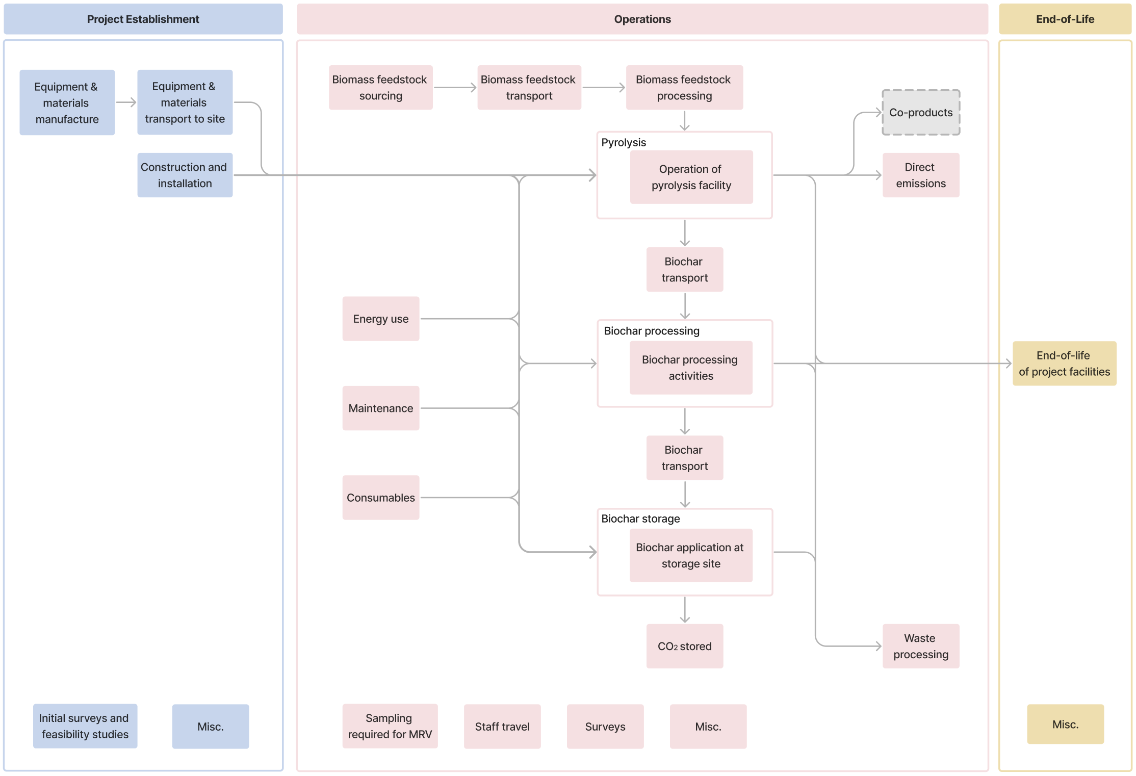
Table 1. Scope of activities and GHG SSRs to be included in the system boundary
| Activity | GHG Source, sink or reservoir | GHG | Scope | Timescale of emissions and accounting allocation |
|---|---|---|---|---|
Project Establishment | Equipment and materials manufacture | All GHGs | Embodied emissions associated with equipment and materials manufacture for project establishment (lifecycle modules A1-314). To include product manufacture emissions for equipment, buildings, infrastructure and temporary structures. | Before project operations start - must be accounted for in the first Reporting Period or amortized in line with allocation rules (See Section 8.6.1) |
Equipment and materials transport to site | All GHGs | Transport emissions associated with transporting materials and equipment to the Project site(s) (lifecycle module A414). | ||
Construction and installation | All GHGs | Emissions related to construction and installation of the project site(s) (lifecycle module A514). To include energy use for construction, installation and groundworks, as well as waste processing activities and emissions associated with land use change. | ||
Initial surveys and feasibility studies | All GHGs | Any embodied, energy and transport emissions associated with surveys or feasibility studies required for establishment of the project site. | ||
Misc. | All GHGs | Any SSRs not captured by categories above, for example staff transport. | ||
Operations | Biomass feedstock sourcing | All GHGs | Any embodied, energy and transport emissions associated with biomass cultivation and harvesting. | Over each Reporting Period - must be accounted for in the relevant Reporting Period (See Section 8.6.2) |
Biomass feedstock transport | All GHGs | Transport of biomass including to biomass processing site and all other transport of biomass ahead of biochar production. | ||
Biomass feedstock processing | All GHGs | Any embodied, energy and transport emissions associated with biomass feedstock processing. | ||
| Pyrolysis | All GHGs | Emissions associated with pyrolysis including:
| ||
Direct emissions | All GHGs | Direct emissions released during pyrolysis. See Section 10.1.1 for calculation details. | ||
Biochar processing | All GHGs | Emissions associated with biochar processing and characterization including:
| ||
Biochar transport | All GHGs | All transport of biochar including to biochar processing site and to the biochar storage site. | ||
Biochar storage | All GHGs | Emissions associated with biochar storage (e.g. spreading on agricultural fields) including:
| ||
CO₂ Stored | CO₂ only | The gross amount of CO₂ removed and durably stored from a biochar project over a Reporting Period. | ||
Sampling required for MRV | All GHGs | Any embodied, energy and transport emissions associated with sampling for MRV purposes, including transportation to collect samples, shipping of samples for laboratory analysis and sample processing. | ||
Staff travel | All GHGs | Flight, car, train or other travel required for the project operations, including contractors and suppliers required on site. | ||
Surveys | All GHGs | Equipment, energy use and transport associated with surveys e.g. ecological surveys. | ||
| Misc. | All GHGs | Any SSRs not captured by categories above. | ||
| End-of-Life | End-of-life of project facilities | All GHGs | Anticipated end-of-life emissions (lifecycle modules C1-414). To include deconstruction and disposal of the project site(s), equipment, vehicles, buildings or infrastructure. | After Reporting Period - must be accounted for in the first Reporting Period or amortized in line with allocation rules (See Section 8.6.3) |
| Misc. | All GHGs | Any emissions SSR not captured by categories above. |
Miscellaneous GHG emissions are those that cannot be categorized by the GHG SSR categories provided in Table 1. The Project Proponent is responsible for identifying all sources of emissions directly or indirectly related to project activities and must report any outside of the SSR categories identified as miscellaneous emissions.
Emissions associated with The Project's impact on activities that fall outside of the system boundary of The Project must also be considered. This is covered under Leakage in Section 8.6.4.
In some instances, the project activities may be integrated into existing activities, such as biochar spreading while tilling. Activities that were already occurring, and would continue to occur in the absence of The Project, may be omitted from the system boundary of the GHG accounting if evidence of this is provided.
In line with the GHG Accounting Module v1.0, the Project must:
- Consider all GHGs associated with SSRs, in alignment with the United States Environmental Protection Agency’s definition of GHGs, which includes: carbon dioxide (CO₂), methane (CH4), nitrous oxide (N20) and fluorinated gasses such as hydrofluorocarbons (HFCs), perfluorocarbons (PFCs), sulfur hexafluoride (SF6) and nitrogen trifluoride (NF3). For CO2 stored, only CO2 shall be included as part of the quantification. For all other activities all GHGs must be considered. For example, the release of CO2, CH4, and N2O is expected during diesel consumption;
- Quantify emissions in tonnes CO₂ equivalent (t CO₂e) using the 100-year Global Warming Potential (GWP) for the GHG of interest, based on the most recent volume of the IPCC Assessment Report (currently the Sixth Assessment Report); and
- Consider materiality of SSRs in line with Isometric requirements.
7.2
Baseline
The baseline scenario for biochar projects assumes that the activities associated with the biochar Project do not take place and that any infrastructure associated with the biochar Project is not built.
Counterfactual storage assesses the CO2 that would have remained durable stored as biogenic carbon in the absence of the Project. This durably stored portion is ineligible for crediting as it is not environmentally additional. The counterfactual storage of all feedstocks must be quantified according to the Biomass Feedstock Accounting Module.
See Section 3 of the Biomass Feedstock Accounting Module for requirements.
8.0
Net CDR Calculation
8.1
Calculation Approach and Reporting Period
The Reporting Period, RP, for biochar projects represents the interval of time over which removals are calculated and reported for verification. The equations used to calculate net CO2e removals will pertain to all GHG emissions and CO2 removals occurring over a Reporting Period. In most cases, the Reporting Period represents a timeframe covering a complete cycle of activities, including biomass feedstock sourcing, pyrolysis, biochar processing, and biochar storage.
For all storage pathways associated with biochar, it is necessary to calculate the total carbon (as CO2e) stored in the biochar (). Guidelines for determining are provided in Section 8.3.1. These calculations depend on methodologies outlined in the relevant Storage Module and therefore must be applied in conjunction with the relevant storage module calculations.
In addition to quantification, an initial characterization is required to determine the amount of CO2 durably removed through biochar production. The specific requirements and methodologies for this assessment are provided in the relevant Storage Module.
GHG emission calculations must include all emissions related to the project activities that occur within the Reporting Period. This includes: (a) any emissions associated with project establishment allocated to the Reporting Period (See Section 8.6.1) (b) any emissions that occur within the Reporting Period (See Section 8.6.2), (c) any anticipated emissions that would occur after the Reporting Period that have been allocated to the Reporting Period (See Section 8.6.3) and (d) leakage emissions that occur outside of the system boundary that are associated with the Reporting Period (See Section 8.6.4).
Total net CO2e removal is calculated for each Reporting Period, and is written hereafter as . The final net CO2e removal quantification must be conservatively determined, giving high confidence that at a minimum, the estimated amount of CO2e was removed.
In line with the Isometric Standard, this Protocol requires that Removal Credits are issued ex-post. Credits may be issued once CO₂ has been durably stored in the identified storage reservoir.
8.2
Calculation of CO₂eRemoval, RP
Net CO2e removal for the production of biochar and its durable storage for each Reporting Period, , can be calculated by Equation 1.
(Equation 1)
Where:
- - the total net CO2e removal for the Reporting Period, RP, in tonnes of CO2e.
- - the total CO2 removed from the atmosphere and stored as organic carbon in the biochar for the RP, in tonnes of CO2e.
- - the total counterfactual CO2 removed from the atmosphere and stored as organic carbon in the absence of the Project for the RP, in tonnes of CO2e.
- - the total GHG emissions for the RP, in tonnes of CO2e.
Reversals which occur after Credits have been issued are separately accounted for by the Buffer Pool, and are therefore not included in Equation 1. Risk of reversal information is given in Appendix 1: Risk of Reversal Questionnaire, with further information provided in Section 5 of the Biochar Storage in Agricultural Soils Module
8.3
Calculation of CO₂eStored, RP
The method of calculation for will depend on the method of storage. Refer to the relevant storage Module for requirements (see Section 12).
8.3.1
Calculation of Cbiochar
The process of biochar production can be divided into several units from which Cbiochar can be calculated. These are:
- The production batch, , which typically consists of utilizing a single type of biomass feedstock, or a consistent blend of multiple feedstocks. This is subsequently converted to biochar through pyrolysis, and transported to a storage site for storage. The unique characteristics of the biomass used, the pyrolysis process, the produced biochar characteristics, transportation distances, and storage site characteristics will be the same for all of the biochar within a Production Batch. The term “Production Process” refers to the complete sequence of activities and operations that result in the creation of a “Production Batch.”
- The production process, this refers to the systematic and consistent sequence of steps and methods used to convert biomass feedstock into biochar through pyrolysis. It is a collective set of biochar production batches generated using the same feedstock and under consistent pyrolysis conditions producing a stable and consistent output of biochar.
- Storage batch, this refers to biochar that is stored together, this may either be constituted of a single production batch, or multiple production batches () blended together prior to storage.
can be calculated for either at the production batch or storage batch (i.e. a blend of biochar) level, Project Proponents must justify their intended approach in the PDD. The two approaches are set out in the following sections:
8.3.1.1
At the Production Batch
Where biochar Production Batches are not blended prior to storage, is calculated as follows:
(Equation 2)
Where:
- - the total CO2 removed for batch , in tonnes of CO2e
- - the concentration of C in the biochar stored in the production batch as weight percent
- - the total mass of biochar emplaced for storage from the production batch , in tonnes
- - stoichiometric conversion factor from carbon mass to CO₂ equivalent mass (molecular weight ratio)
8.3.1.2
At the Storage Batch
The total amount of CO2 contained in the stored biochar can be calculated as follows.
Where all biochar production batches are blended prior to storage:
(Equation 3)
Where:
- - Storage Batch identifier
- - Production Batch identifier
- - the total CO₂ equivalent removed for storage batch n, in tonnes of CO₂e
- - the concentration of carbon in the biochar from production batch p, as weight percent
- - the total mass of biochar from production batch included in storage batch , in tonnes
- - stoichiometric conversion factor from carbon mass to CO₂ equivalent mass (molecular weight ratio)
8.3.2
Frequency of Measurement
This Protocol provides two alternative methods for measuring and quantifying carbon content frequency. Method A requires measuring the carbon content of every production batch. Method B involves sampling only a representative proportion of production batches and applying conservative estimates to determine the carbon content of unsampled batches.
8.3.2.1
Method A: Sampling Every Batch
Using this method, the organic carbon content of a Production Batch must be determined through direct measurement, using one of the following approaches:
-
Single-batch sampling
- For unblended biochar, which by definition originates from a single Production Batch, the biochar is sampled directly, and no further calculation is required.
-
Multiple-batch sampling
- Where a Storage Batch is formed by blending biochar from multiple Production Batches, samples must be collected from each constituent Production Batch.
- The carbon content of the entire Storage Batch is then determined using a mass-weighted average of the carbon contents of the individual Production Batches, as calculated in Equation 3
8.3.2.1.1
Sampling Requirements
Refer to the section “Minimum Number of Samples per Batch” for requirements on the acceptable minimum number of samples per Production Batch.
- If multiple samples are taken per Batch, the mean must be used in calculations.
- All supporting data used to calculate averages must be documented and reported.
8.3.2.2
Method B: Sampling a Production Process
For a given Production Process using a specific feedstock, samples must be collected from an agreed-upon number of initial Production Batches, using Method A. This initial sampling is required to generate sufficient data to estimate the carbon content of future Production Batches with an appropriate level of statistical confidence. The sample size must be determined through consultation with Isometric, with a minimum requirement of 30 samples. Until this threshold is reached, Method A must be used.
Once the required initial dataset has been established, ongoing sampling must occur at a minimum frequency of one sample for every 10 Production Batches.
In exceptional cases, a different sampling frequency may be agreed upon with Isometric prior to verification, provided that the Production Process conditions can be demonstrated to remain stable throughout the Project.
For the acceptable minimum number of samples to take per Batch, see minimum number of samples per Batch below.
8.3.2.2.1
Conservative Estimation of Carbon in Unsampled Batches
For batches which are not sampled, carbon content must be conservatively estimated, as follows:
(Equation 4)
(Equation 5)
Where:
- - the standard error of the mean of carbon content, across all eligible samples for this Production Process
- - the standard deviation of carbon content, across all eligible samples for this Production Process
- - the number of eligible samples for this Production Process
- - the mean carbon content of all eligible samples for this Production Process
Eligible samples are those taken in the previous 6 months before a specific Production Batch was produced. Older samples may not be used.
8.3.2.2.2
Treatment of Carbon Content Measurement Outliers
This process applies only when Method B is used to calculate carbon content and must be applied to all carbon content measurements used in those calculations, regardless of which production batches were sampled.
For a given Production Process, an outlier is defined as any individual carbon content measurement, , that lies more than three standard deviations () above or below the mean ():
To minimize the influence of extreme measurements, all outliers must be adjusted using winsorization, defined as follows:
- If , set .
- If , set .
The winsorized measurement must then be used in all carbon content calculations.
Calculation of and :
- and must be calculated from all historical carbon content measurements from the same production process taken within the six months preceding the removal date for which the carbon content is being calculated.
- When estimating carbon content for a sampled batch, only historical measurements should be used to calculate and . Samples from the batch currently being calculated must not be included.
- must be calculated using the sample standard deviation formula.
Winsorization may only be applied after a minimum of 30 measurements have been collected for the relevant production process to ensure statistical significance.
The Project Proponent must:
- Track the frequency and distribution of outliers across Production Batches.
- Investigate if the number of outliers significantly exceeds the statistically expected frequency, as this may indicate a systematic issue with the Production Process or measurement method.
- Provide supporting evidence and corrective actions if requested during verification. Verification bodies (VVBs) may review outlier monitoring at their discretion.
8.3.2.2.3
Sampling Requirements
- Sample Eligibility
- Only samples collected within 6 months prior to a specific Production Batch may be used for carbon content estimation. Samples older than 6 months are not eligible.
- Random Sampling Protocol
- All batches must undergo random sampling to ensure representative carbon content measurements across production.
- The random sampling approach requires agreement with Isometric and documented in the Project Design Document.
- Compliance Triggers
- A project review by Isometric will be triggered if either condition occurs within a 6-month period:
- Project Proponent fails to conduct required sampling on 3 or more occasions
- More than 3 measurements fall below 3 standard deviations from the mean
- Production Process Changes
- A feedstock must be treated as a new Production Process (requiring fresh sampling with all prior data invalidated) when:
- Significant changes are made to the production process that could alter average carbon content
- Significant deviations in carbon content are detected (as defined in compliance triggers above)
- A feedstock must be treated as a new Production Process (requiring fresh sampling with all prior data invalidated) when:
- When a new Production Process is established, sampling must restart from zero with no historical data carried forward.
8.3.3
Minimum Number of Samples Per Batch
For all measurements, samples must be collected from a well-mixed and representative aliquot of the biochar. To account for potential variation within a single Production Batch, one of the following approaches must be adopted:
- Multiple-Sample Approach (preferred)
- A minimum of three samples must be collected from each measured Production Batch.
- These samples must be representative of the full range of physical characteristics present in the batch (e.g., particle size, color, texture).
- Justification of Minimal Within-Batch Variation (Must be agreed with Isometic in advance)
- Where fewer than three samples are collected, the Project Proponent must provide justification and supporting evidence demonstrating that within-batch variability is likely to be minimal.
- Acceptable justification may include:
- Documentation of the physical characteristics and consistency of the Production Process, or
- Data demonstrating low variability in carbon content within the Production Batch.
8.3.4
Ensuring representative sampling
Samples must accurately represent materials designated for the storage pathway that will form the basis for credit quantification. Biochar should be sampled in its final pre-storage condition, i.e., post-processing and at typical moisture levels. For storage in agricultural soils involving co-application with other substances (such as compost), sampling should occur before the blending process is performed.
8.4
Measurement of Mass of Biochar Stored
The measurement of mass stored will depend on the storage Module being used. As such, it is for the Project Proponent to describe and justify their stated method of measurement in the PDD. Below are examples of accepted methods.
Preferred Method: Weighbridge Measurement
- The mass of applied biochar is determined by weighing delivery trucks using calibrated scales at the application or delivery site. This measurement serves dual purposes:
- Proof of delivery to the storage/application site
- Accurate mass determination via difference between loaded and unloaded truck weights
- Scale Certification Requirements
- All truck scales must maintain current certification under applicable local, state, or federal legal-for-trade regulations. Testing and calibration must:
- Use certified weights meeting NIST Handbook 4415 specifications
- Be performed by state-certified entities
- Comply with all relevant local, state, and federal regulations
- All truck scales must maintain current certification under applicable local, state, or federal legal-for-trade regulations. Testing and calibration must:
Alternative Method: Documentation-Based Verification
- When truck scales are unavailable at the application or delivery site, Isometric may pre-approve alternative proof of delivery consisting of:
- Signed delivery receipt documents
- Bills of lading
- Photographic evidence of delivery
When using this alternative method, the Project Design Document (PDD) must detail:
- All weight measurement procedures to be conducted at the production site
- Transportation protocols and precautions to prevent mass loss during transit
- Chain of custody documentation
8.4.1
Required Documentation - CO2eStored, RP
The Project Proponent must maintain the following records as evidence of gross CO₂e stored in applied biochar:
- Delivery Records:
- Weigh scale tickets showing arrival and departure weights for each biochar delivery, or equivalent documentation
- Carbon Content Analysis:
- Analytical results from ASTM D5291 (or equivalent) carbon content analysis for each required batch
- Incident Documentation:
- Records of any spills during application operations, including quantity estimates of material released
All carbon analysis results and application mass records (including weigh scale tickets) must be retained by the Project Proponent for verification purposes for a minimum of five years.
8.4.1.1
Production and Storage Monitoring
Biochar production, transportation, and storage processes must be continuously monitored to identify and document:
- Process upsets or equipment failures
- Resulting biochar spills or losses
- Quantification of lost material
Any deviations should be reported to Isometric as soon as reasonably possible after discovery.
8.4.1.2
Loss Accounting
When process upsets result in biochar loss:
- Quantify the Loss: Measure and document the amount of biochar lost from each affected batch
- Adjust Delivery Records: Deduct the quantified loss from the delivered biochar amount recorded on delivery weigh tickets
- Allocate to Aplications: Apply loss deductions directly to the specific biochar applications affected by each batch
- GHG Statement: Account for all documented losses in the GHG Statement for the relevant Project batch
This ensures that only successfully delivered and stored biochar is credited for carbon storage in the project's GHG accounting.
8.5
Calculation of CO₂eCounterfactual, RP
Type: Counterfactual
describes the CO2 that would have been removed from the atmosphere and stored beyond 15 years in the baseline scenario.
The calculation of is determined by the requirements outlined in Section 2 of the Biomass Feedstock Accounting Module.
See Biomass Feedstock Accounting Module for calculation of .
8.6
Calculation of CO2eEmissions,RP
Type: Emissions
is the total quantity of GHG emissions from operations and allocated embodied emissions for each Reporting Period . This can be calculated as:
(Equation 6)
Where:
- - the total GHG emissions for a Reporting Period, RP, in tonnes of CO2e.
- - the total GHG emissions associated with project establishment for a RP, in tonnes of CO2e, , see Section 8.6.1.
- - the total GHG emissions associated with operational processes for a RP, in tonnes of CO2e, see Section 8.6.2.
- - the total GHG emissions that occur after the RP and are allocated to the RP, in tonnes of CO2e, see Section 8.6.3.
- - the GHG emissions associated with the Project’s impact on activities that fall outside of the system boundary of a Project, over a given RP, in tonnes of CO2e, see Section 8.6.4.
The following sections set out specific quantification requirements for each variable.
8.6.1
Calculation of CO₂eEstablishment, RP
GHG emissions associated with should include all historic emissions incurred as a result of project establishment, including but not limited to the SSRs set out in Table 1.
Project establishment emissions occur from the point of project inception through to before the first removal activity takes place. GHG emissions associated with project establishment may be allocated in one of the following ways, with the allocation method selected and justified by the Project Proponent in the PDD:
- As a one time deduction from the first Reporting Period
- Allocated to removals as annual emissions over the anticipated project lifetime; or
- Allocated per output of product (i.e., per tonne CO₂ removed) based on estimated total production over project lifetime.
The anticipated lifetime of The Project should be based on reasonable justification and should be included in the PDD to be assessed as part of project validation.
Allocation of emissions to removals must be reviewed at each Crediting Period renewal and any necessary adjustments made. If the Project Proponent is not able to comply with the allocation schedule described in the PDD (e.g., due to changes in delivered volume or anticipated project lifetime), the Project Proponent should notify Isometric as early as possible in order to adjust the allocation schedule for future removals. If that is not possible, the Reversal process will be triggered in accordance with the Isometric Standard, to account for any remaining emissions.
8.6.2
Calculation of CO₂eOperations, RP
GHG emissions associated with should include all emissions associated with operational activities including but not limited to the SSRs set out in Table 1. This includes direct emissions from pyrolysis, , for which calculation and measurement details are set out in Section 10.1.1.
For biochar projects, the Reporting Period begins when the activity associated with a batch of Removals begins, and ends upon application of biochar from that batch at the storage site. As an example, for Projects storing biochar in agricultural soils, the Reporting Period begins with biomass feedstock sourcing and ends with biochar application to agricultural soils. The Reporting Period may cover a set period of time, for example a one month period of activity, inclusive of biomass sourcing through to application on agricultural soils for batches of Removals that fall into that month.
emissions must be attributed to the Reporting Period in which they occur. Allocation may be permitted in certain instances, on a case by case basis, in agreement with Isometric.
8.6.3
Calculation of CO₂eEnd-of-life, RP
includes all emissions associated with activities that are anticipated to occur after the Reporting Period, but are directly or indirectly related to the Reporting Period. For example this could include end-of-life emissions for project facilities (indirectly related to all deployments).
GHG emissions associated with may occur from the end of the Reporting Period onward, and typically through to completion of project site deconstruction and any other end-of-life activities.
GHG emissions associated with activities that are directly related to each deployment must be quantified as part of that Reporting Period. GHG emissions associated with activities that are indirectly related to all deployments may be allocated in the same ways as set out in .
Given the uncertain nature of emissions, assumptions must be revisited at each Crediting Period and any necessary adjustments made. Furthermore, if there are unexpected emissions associated with a Reporting Period, or The Project as a whole, that occur after The Project has ended, then the Reversal process will be triggered to compensate for any emissions not accounted for.
8.6.4
Calculation of CO₂eLeakage, RP
includes emissions associated with a Project's impact on activities that fall outside of the system boundary of a Project.
It includes increases in GHG emissions as a result of The Project displacing emissions or causing a knock on effect that increases emissions elsewhere. This includes emissions associated with activity-shifting, market leakage and ecological leakage.
It is the Project Proponent's responsibility to identify potential sources of leakage emissions. At a minimum, biochar Projects must account for market leakage emissions associated with biomass feedstocks in accordance with the Biomass Feedstock Accounting Module.
emissions must be attributed to the Reporting Period in which they occur. Allocation may be permitted in certain instances, on a case by case basis in agreement with Isometric.
8.6.5
Emissions Accounting Requirements
8.6.5.1
Considerations for Waste Input Emissions
Embodied emissions associated with system inputs considered to be waste products can be excluded from the accounting of the GHG Statement system boundary provided the appropriate eligibility criteria are met.
For waste energy inputs, for example the use of waste heat, refer to the Energy Use Accounting Module v1.2.
Refer to Energy Use Accounting Module for the calculation guidelines.
All biomass feedstock must be eligible and accounted for according to the Biomass Feedstock Accounting Module v1.3.
See Biomass Feedstock Accounting Module for eligibility criteria.
For all other waste inputs, refer to Section 6.3 of the GHG Accounting Module v1.0.
See GHG Accounting Module for eligibility criteria.
8.6.5.2
Co-product Allocation
The biomass pyrolysis process may result in the production of co-products, such as bio-oil, pyrolysis gas (bio-gas), electricity and heat.
Projects must follow the co-product allocation procedures described in Section 6.1 of the GHG Accounting Module v1.0. For projects where all co-products have a measurable energy content, the optional procedure outlined in Section 8.6.5.2.1 may be applied instead of the Procedures outlined in Section 6.1 of the GHG Accounting Module v1.0 .
8.6.5.2.1
Emissions Allocation based on Energy Content
Emissions allocation may be undertaken based on energy content in instances where all co-products, including CDR products, have a measurable energy content which can be expressed in Megajoules (MJ). Where this is not the case for all co-products, no allocation should be made based on energy content. In this section Net Calorific Value is defined as the amount of energy released by complete combustion, assuming the water vapor produced during combustion is not condensed and used.
Equation 7 sets out the calculation procedure to be followed to apply emissions allocation based on energy content. When this procedure is followed, the term in Equation 1 in Section 8.2 should be calculated based on Equation 7.
(Equation 7)
Where:
, , and are calculated as per the relevant sections of this Protocol.
is the fraction of emissions assigned to the CDR product, represented as:
(Equation 8)
Where:
is the energy content of the CDR product, equal to the Net Calorific Value, expressed in MJ/kg.
is the energy content of a specific output, expressed in MJ.
- For electricity outputs, this should be equal to the total quantity of electricity exported over the Reporting Period, converted to MJ;
- For heat this should be equal to the Net Useful Thermal Output exported over the Reporting Period, expressed in MJ; and
- For all other outputs, this should be equal to the Net Calorific Value multiplied by the quantity of product produced and exported over the Reporting Period, expressed in MJ.
- represents the product
8.6.5.3
Energy Use Accounting
This section sets out specific requirements relating to quantification of energy use as part of the GHG Statement. Emissions associated with energy usage result from the consumption of electricity or fuel.
Examples of electricity usage may include, but are not limited to:
- Electricity consumption for pyrolysis activities;
- Processing equipment, motors, drives and instrumentation;
- Biomass pre-treatment, drying, densification or particle size reduction;
- Facility operations;
- Pyrolysis system start up;
- Electricity for building operation & management; and
- Electricity consumption for any biochar processing activities at the pyrolysis site or application site.
Examples of fuel consumption may include, but are not limited to:
- Pyrolysis system start up;
- Pyrolysis reactor heating;
- Emission control (e.g. propane for flare co-firing or pilot);
- Handling equipment, such as fork trucks or loaders; and
- Fuel consumption of agricultural machinery for spreading.
The Energy Use Accounting Module v1.2 provides requirements on how energy-related emissions must be calculated in a CDR Project. It sets out the calculation approach to be followed and acceptable emissions factors.
Refer to Energy Use Accounting Module for the calculation guidelines.
8.6.5.4
Transport Emissions Accounting
This section sets out specific requirements relating to quantification of emissions related to transportation.
Emissions associated with transportation include transportation of products and equipment as part of a Reporting Period process. Examples may include, but are not limited to:
- Transportation of biomass to pyrolysis facility;
- Transportation of pyrolyzed biochar to storage site; and
- Transportation and shipping related to collecting samples for characterization.
The Transportation Emissions Accounting Module v1.1 provides requirements on how transportation-related emissions must be calculated in a CDR Project so that they can be subtracted in the net CO2e removal calculation. It sets out the calculation approach to be followed and acceptable emissions factors.
Refer to Transportation Emissions Accounting Module for the calculation guidelines.
8.6.5.5
Embodied Emissions Accounting
This section sets out specific requirements relating to quantification of embodied emissions as part of the GHG Statement. Embodied emissions are those related to the life cycle impact of equipment and consumables.
Examples of project-specific materials and equipment that must be considered as part of the embodied emission calculation include but are not limited to:
- Process inputs or consumables:
- Catalysts;
- Water (for biomass pre-treatment or reactor cooling, not to be used during pyrolysis);
- Thermal oils used for heat transfer;
- Coolants used for biochar quench; and
- Gasses such as nitrogen used for process or instrumentation purges.
- Gasses, reagents or other materials used for operation of monitoring equipment and on-site analyzers; and
- Equipment:
- Pyrolysis reactor;
- Feedstock conveyors, augers, feed bins, and related equipment;
- Biochar quench or condenser units, including any heat transfer equipment, such as glycol chillers and pumps;
- Offgas emissions control systems, such as flares or oxidizers;
- Preparation or mixing equipment;
- Pumps, piping, and related equipment;
- Storage tanks;
- All support structures, facilities, and infrastructure, including steel platforms, framing, supports, concrete footings and building structures; and
- On-line analyzers, measurement equipment, or other such devices.
The Embodied Emissions Accounting Module v1.0 sets out the calculation approach to be followed including allocation of embodied emissions, life cycle stages to be considered, data sources and emission factors.
Refer to Embodied Emissions Accounting Module for the calculation guidelines.
9.0
Pyrolysis Reactor System Requirements
9.1
Acceptable Technologies
There are a wide range of technologies available for achieving pyrolysis of solid biomass. These may be characterized into "slow pyrolysis" and "fast pyrolysis" based on the heating rate and residence time of biomass in the pyrolysis chamber. Slow pyrolysis processes are ideal to maximize the yield of pyrolysis towards the solid biochar product, and minimize the production of bio-oil and pyrolysis gasses, however both "slow" and "fast" pyrolysis processes may be eligible under this Protocol. Technology may also be characterized by its technology level (low- mid or high- technology) based on the reactor design, as well as the level of automation, and application of sensors and monitoring equipment. Equally, processes may be either continuous (ongoing with a regular flow of feedstock through the system), or batch (non-continuous) based.
This Protocol does not explicitly specify the type of reactor or technology level required, Project Proponents must be able to meet the monitoring requirements set out below and reactor designs, including the reactor type, expected materials specifications and engineering design diagrams must be described in the PDD.
Biochar can be produced using a wide range of technologies that vary in scale, level of automation, and intended outputs. Some reactor systems are specifically designed to produce biochar as the primary product of the process. These tend to be more centralized, higher-technology solutions that allow for precise control of operating parameters such as temperature, residence time, and oxygen levels, resulting in consistent product quality and higher levels of process monitoring. A summary of common reactor types is found in Table 5.
Table 5: Overview of common reactor types
| Reactor type | Description |
|---|---|
| Fixed-bed reactor | Solid biomass is loaded into a vessel. Heat is applied to the vessel to increase the temperature of the biomass. Once the target pyrolysis temperature is reached, and potentially sustained for some period of time, the solid biochar product is collected in a batch-mode. Gaseous and solid products self-separate within the reactor. |
| Auger reactor | Solid biomass is continuously fed to and transported through a cylindrical vessel using a screw-type fitting. Heat is applied to the exterior of the vessel. As biomass is transported along the length of the reactor, its temperature is increased. The target pyrolysis temperature is reached at the product exit point from the reactor. Gaseous and solid products are collected and separated at the reactor outlet. The biochar product is collected continuously. |
| Rotary kiln reactor | Solid biomass is continuously loaded at the top of an inclined rotating drum. As more biomass is added to the vessel, biomass inside the vessel is transported downwards. Heat is applied to the exterior of the vessel. As biomass is transported along the length of the reactor, its temperature is increased. The target pyrolysis temperature is reached at the product exit point from the reactor. Gaseous and solid products self-separate at the reactor outlet. The biochar product is collected continuously. |
This Protocol recognizes the diversity of production approaches and establishes performance-based requirements to ensure that, regardless of technology type or scale, environmental safeguards, product quality, and monitoring standards are maintained.
Additional styles of project may also include:
Refers to the Biochar Production in Distributed and Small Scale Projects for the additional MRV requirements.
Refers to the Biochar Production in Combustion Co-product Systems for the additional MRV requirements.
9.2
System Design Requirements
9.2.1
Design Diagram Requirements
An engineering design diagram of the Project pyrolysis reactor design(s) must be included in the PDD. The diagram must clearly show:
- Reactor dimensions and overall layout.
- Locations of material inflows and outflows.
- Positions of sensors used to monitor temperature and pressure.
- Details of internal equipment, such as agitators or heating/cooling coils.
- Details of external heat transfer equipment, including heat exchange fluid entry and exit points, along with corresponding sensors for flow rate and temperature.
The diagram must include sufficient viewpoints to illustrate the placement of all key components. Additionally, any other process equipment essential for the safe and effective operation of the pyrolyzer should also be included and clearly highlighted.
In instances where Project Proponents wish to expand an existing Project, or to submit a new Project for validation, where the reactor vessels used to achieve pyrolysis of biomass are manufactured according to the same design diagrams as those submitted for initial project validation, it is not necessary to resubmit a new design diagram at each subsequent validation event. In cases where the design of the reactor vessel differs to that from the original project validation, submission of updated design diagram documentation is required.
9.2.2
Construction Considerations
It is anticipated that the pyrolyzer will operate at high temperatures and may also operate at elevated pressures. Therefore, appropriate design considerations must be implemented to ensure the mechanical integrity and safe operation of the reactor to mitigate potential adverse operational conditions.
The PDD must include detailed information on the selection of materials used for each reactor component, along with a justification of these choices from the perspectives of thermal and mechanical resilience.
For reactors operating at pressures above atmospheric levels, the design must address:
- The operating pressure range and limits.
- The shape and size of the pressure vessel.
- The positioning of material inlets and outlets.
- The placement of temperature and pressure sensors.
These considerations are essential to ensure the mechanical integrity and safe operation of the reactor.
All design measures must comply with an appropriate local standard governing the design and fabrication of pressure vessels, such as 2014/68/EU (the Pressure Equipment Directive) or an equivalent regional standard applicable to the project’s location. If no suitable regional standard exists, Project Proponents are required to follow the 2014/68/EU standard.
9.2.3
Reactor Maintenance
An appropriate reactor maintenance plan must be established and fully documented in the PDD. The plan should describe how the Project Proponent will ensure the structural integrity of the reactor vessel in order to prevent potential material loss events.
The maintenance plan must include:
- Procedures for monitoring mechanical and thermal degradation of reactor components.
- Mitigation measures to address identified risks that could lead to vessel failure.
- Preventive maintenance schedules to reduce the likelihood of material release into the environment.
If applicable, all maintenance activities must comply with an applicable local standard governing the inspection and maintenance of pressure vessels, such as 2014/68/EU (the Pressure Equipment Directive) or an equivalent regional standard relevant to the project’s location. If no such regional standard exists, the 2014/68/EU standard must be applied.
10.0
Emissions Testing Requirements
This section sets out the permissible ultimate fate of requirements for the measurement and quantification of gaseous pyrolysis gas loss from the reactor and the calculation of the direct carbon emissions from pyrolysis.
10.1
Operation Emissions
The thermochemical conversion of solid biomass to produce biochar through pyrolysis also produces gaseous co-products. Depending on the pyrolysis conditions and feedstock, the gaseous phase may contain both volatile condensable components (bio-oil) and non-condensable components (pyrolysis gasses; predominantly CH4, with N2O, CO, CO2 and light hydrocarbons). Depending on the specific technologies deployed by the Project, there are various options for handling the gaseous co-product eluted from the pyrolysis unit. Permissible options for the measurement and handling the gaseous product and emissions accounting requirements associated requirements are detailed in this Section.
N2O is a potent greenhouse gas, which may be formed during pyrolysis of feedstocks with low C/N ratios. The presence of substantial reactive or labile N is a key precursor to N2O formation in the flue gas. While there is no accepted threshold in the scientific literature below which N2O emissions from flue gas becomes a concern, typically this is at C/N ratios under 30; examples of feedstock with this ratio may include, but are not limited to; manure, biosolids or seaweed. The Project Proponent must justify why N2O is not a significant concern if they do not plan to monitor its concentration in the flue gas.
Project Proponents must secure and maintain all required permits and approvals related to air emissions, combustion equipment, and other applicable air quality regulations for biochar production. They shall provide supporting documentation, such as permits, inspection reports, or emissions test results, demonstrating compliance with local, regional, and national air pollution control requirements. Projects must also ensure ongoing adherence to these regulations throughout the crediting period, updating documentation as permits are renewed or amended.
10.1.1
Quantification of Emissions
This section details the two acceptable methods of quantifying the Direct Emissions from a pyrolysis process, either through direct continuous measurement or regular emissions testing.
10.1.1.1
Option 1 - Direct Continuous Measurement CO2e, RP
Direct measurement is the primary and preferred method for quantifying .
Emissions should be calculated as follows:
(Equation 9)
Where:
- - the total amount of non-CO2 GHG emissions associated with the release of pyrolysis gasses directly to the atmosphere, via combustion in an emissions control unit, or via combustion for the provision of thermal energy within the process, during a Reporting Period, , in tonnes of CO2e, measured directly.
- - the total mass flow rate of gas emitted to the atmosphere during time period , in tonnes per hour. Measurement must be made immediately upstream of the point of emission to the atmosphere.
- - the concentration of species in the emitted gas during time period , expressed as a mass fraction. Measurement must be made immediately upstream of the point of emissions to the atmosphere.
- - the 100-year global warming potential of species .
- - the duration of time period , in hours.
- - the total number of species in the emitted gas stream.
- - the total number of time periods comprising the Reporting Period, .
Note: Direct emissions reported under this section include non-CO2 greenhouse gases only, as CO2 emissions are accounted for separately to avoid double counting. CO2 released during pyrolysis is reflected in reductions to stored carbon (), which determines net CO2e removal and crediting.
10.1.1.1.1
Measurement Requirements
Quantification of requires two primary measurements:
-
Gas Flow Rate ()
- Measured immediately upstream of the emission point using a continuous inline meter (e.g., coriolis, thermal mass) which must be:
- Factory-calibrated for expected gas composition
- Accurate to ±2% full scale
- Able to record at a frequency of ≥ 1-minute intervals
- Calibrated at least annually, traceable to national standards
- Installation to manufacturer guidelines (e.g., straight-pipe distances)
- Raw data must be retained and made available on request.
- Measured immediately upstream of the emission point using a continuous inline meter (e.g., coriolis, thermal mass) which must be:
-
Gas Composition ()
- CH4, N2O, CO, and CO2 measured immediately upstream of emission point using a continuous inline analyzer (e.g., NDIR, TDL) which must be:
- Accurate to ±2% full scale
- Able to record at a frequency of ≥ 1-minute intervals
- Calibrated at least annually, traceable to national standards
- Raw data must be retained and made available on request.
- CH4, N2O, CO, and CO2 measured immediately upstream of emission point using a continuous inline analyzer (e.g., NDIR, TDL) which must be:
10.1.1.1.2
Required Records
- The Project Proponent must retain for at least five years:
- Raw flow and composition measurement data for the Reporting Period.
- Calibration records for all meters and analyzers.
- Manufacturer manuals detailing calibration and maintenance procedures.
10.1.1.2
Option 2 - Regular Emissions Testing for CO2eOperations, RP
Where direct measurement is not practically feasible (e.g., highly distributed pyrolysis reactors, remote locations), emissions testing may be used as an alternative method. This measurement will then be applied to all subsequent batches produced, until the next emissions test is performed (with the exception of distributed project, see Section 9.1.1.4).
Emissions should be calculated as follows:
(Equation 10)
Where:
- the total amount of non-CO2 GHG emissions associated with the release of pyrolysis gasses directly to the atmosphere, via combustion in an emissions control unit, or via combustion for the provision of thermal energy within the process, during a Reporting Period, , in tonnes of CO2e, measured using regular emissions testing.
- = measured concentration of species n from the spot test (mass fraction), corrected to the appropriate basis (dry/wet, standard temperature and pressure).
- = gas mass flow rate during the spot test (t/hr), corrected to the same basis.
- = total number of hours the reactor was emitting during the Reporting Period.
Note: Direct emissions reported under this section include non-CO2 greenhouse gases only, as CO2 emissions are accounted for separately to avoid double counting. CO2 released during pyrolysis is reflected in reductions to stored carbon (), which determines net CO2e removal and crediting.
Emissions testing must be conducted by an accredited provider (e.g., ASTM D7036, ISO 17025, or approved by state or regional authority), or if using portable equipment a full calibration certificate should be provided. These tests must be performed at least annually on all reactors/kilns being used by the Project.
Regular Emissions Testing should be representative of actual operations, including quenching if appropriate. Emissions testing is considered representative only if:
- Feedstock Consistency
- Feedstock used in operations must be identical or demonstrably similar to that used in emissions testing.
- Where the biomass feedstocks used during project operations and emissions testing are not the same, analytical testing should be used to demonstrate that they are similar. Analytical testing must follow ASTM D5291 and demonstrate that, for each measured feedstock characteristic, the biomass used in actual project operations falls within ±10% of the corresponding value from the biomass used during emissions testing.
- Process Consistency
- Flue stack temperature during operations must be within ±10% of emissions test values.
Temperature must be measured using a calibrated sensor that is:
- Accurate to ±2% full scale
- Able to record at a frequency of ≥ 1-minute intervals
- Calibrated at least annually, traceable to national standards
Raw data must be retained and made available on request.
10.1.1.2.1
Required Records
The Project Proponent must retain for at least five years:
- Emissions testing reports from accredited entities.
- Raw temperature data for the Reporting Period.
- Calibration records for all measurement equipment.
- Manufacturer manuals detailing calibration and maintenance requirements.
10.1.2
Permissible Routes for Gaseous Emissions
All non-CO2 emissions to the atmosphere, via any of the approaches described in the following Sections, must be converted to tonnes of CO2e using their respective 100-year Global Warming Potential (GWP) for the relevant GHGs, based on the most recent volume of the IPCC Assessment Report (presently the Sixth Assessment Report).
There are four permissible end-use emissions accounting approaches for the produced pyrolysis gasses:
10.1.2.1
Venting
- Venting of pyrolysis gasses directly to the atmosphere.
- Required measurements directly before or at point of emission:
- Gas flow rate
- Composition of the vented gas stream accounting for at least CH4, N2O, CO, and CO2.
10.1.2.2
Venting After an Emissions Control System
- Venting of pyrolysis gasses to the atmosphere via an emissions control system, such as a thermal oxidizer, wet scrubber, electrostatic precipitator or flare stack.
- Required measurements directly before or at point of emission:
- Flow rate
- Composition of the vented gas stream accounting for at least CH4, N2O, CO, and CO2.
10.1.2.3
Combustion of Pyrolysis Gasses for Energy Recovery
- Combustion of pyrolysis gasses within the Project gate to provide thermal energy for operation of the pyrolyzer.
- Required measurements directly before or at point of emission:
- Flow rate
- Composition of the vented gas stream accounting for at least CH4, N2O, CO, and CO2.
- It should be noted that the flue gas from the pyrolyzer heating source may also partially result from co-firing with fuels obtained from outside sources. If the flue gas from the pyrolyzer heating source is directly monitored, it is not necessary to include fuel combustion for heating the pyrolyzer in the calculation of , to avoid double counting. However, the emissions associated with the production and transportation of such fuels must still be accounted for. Bio-oil produced during pyrolysis may also be co-fired using this approach, and can be accounted for in the same way as for the co-firing of pyrolysis gasses.
10.1.2.4
Provision of Gasses to a Third Party Consumer
- Provision of pyrolysis gasses to a downstream consumer for third-party use.
- In this case, the Project Proponent may follow emission allocation procedures (see Section 7.1.1 for allocation calculation details).
10.1.3
Other Pathways of Gaseous Loss
If the reactor operates above atmospheric pressure, the reactor design must incorporate appropriate sensors and monitoring systems to detect and quantify any loss of pyrolysis gases during operation.
10.1.3.1
Leakage Monitoring Requirements
At a minimum, the system must include:
- Sensors at the flue gas outlet to measure the outflow of pyrolysis gases.
- Integration of these measurements with a validated reactor model to:
- Estimate the total pyrolysis gas production; and
- Quantify potential unmonitored or unintentional gas leakage to the environment.
10.1.3.2
Chemical Reactor Model Requirements
The chemical reactor model used to characterize reactor performance and estimate gas losses must:
- Consider all relevant physical and chemical mechanisms specific to the chosen reactor type.
- Include a chemical kinetics model based on the latest scientific understanding for the reactor configuration.
- Be validated using empirical data.
- Incorporate a complete process mass balance, accounting for all product yields.
- Include detailed documentation of the model validation process in the PDD.
10.1.3.3
Alternative Approaches to Leakage Verification
If it is not feasible to develop a high-quality mathematical reactor model, one of the following alternative verification approaches may be used to demonstrate that there is no substantial unintended leakage of pyrolysis gases:
10.1.3.3.1
Continuous System Pressure Monitoring
- Demonstrate that the reactor vessel pressure remains at a consistent pressure during operations.
- Use a calibrated pressure sensor that meets the following requirements:
- Accuracy: ±2% of full scale or better.
- Recording frequency: At least once every 1 minute.
- Calibration:
- Must meet or exceed manufacturer calibration requirements.
- Calibration frequency must be no less than once per year.
- Data availability: Raw pressure data must be retained and made available upon request.
10.1.3.3.2
Regular Leakage Testing
- Conduct periodic leakage testing in compliance with prevailing national or international standards or by an accredited leakage testing authority.
- Acceptable standards include, for example:
- ASTM E1003-13(2022) (Standard Test Method for Hydrostatic Leak Testing), or
- An equivalent standard applicable in the Project region.
- Testing frequency: At least once every 12 months.
- Recordkeeping: Project Proponents must retain proof of testing and results for a minimum of five years.
11.0
Additional Guidance on the Condensable (bio-oil) Fraction
Condensable fractions of the gaseous stream may be separated from the using a condenser, or any other suitable gas-liquid separation unit. The resulting (condensable) liquid-phase is bio-oil, and the (non-condensable) gas-phase is pyrolysis gasses. There are three permissible end-use emissions accounting approaches for the produced bio-oil:
- Storage of the produced bio-oil by injection into natural or engineered subsurface features or geologic storage formations which may include, but are not limited to, reservoirs, saline aquifers, caverns, or mines. Storage of produced bio-oil must be conducted in compliance with the requirements described in the Bio-Oil Geological Storage Protocol. In this case, the Project Proponent may claim Credits for the storage of bio-oil, in addition to the Credits claimed for storage via biochar (as detailed under this Protocol). Where Isometric Credits are generated for both bio-oil injection and biochar resulting from the same thermochemical conversion process, emissions associated with the thermochemical conversion of solid biomass to produce biochar and bio-oil will be allocated proportionately to each storage pathway for the purposes of calculating net-CO2e removal for each (see Section 7.1.1 for allocation calculation details); or
- Provision of produced bio-oil to a downstream consumer for third-party use, such as combustion for heating. In this case, the Project Proponent may follow emission allocation procedures (see Section 7.1.1 of this Protocol for allocation calculation details).
- Treatment of the produced bio-oil downstream and environmental disposal as a waste stream or hazardous waste, following methods compliant to relevant local legislative frameworks. In this case, the Project Proponent must account for all emissions relevant to treatment and disposal of the waste stream (see Section 7.1 of this Protocol).
12.0
Storage
For all information on what chemical and physical characterization of biochar must be carried out, and for calculation of , please refer to the relevant storage Module.
Durability and monitoring requirements for Biochar Storage in Soils Environments.
Durability and monitoring requirements for Biochar Storage in Low Oyxgen Burial Environments.
Durability and monitoring requirements for Biochar Storage in the Built Environment.
13.0
Appendix I: Risk of Reversal Questionnaire
This risk assessment identifies the pathway specific risk factors relevant to a carbon removal project. The relevant risk factors identified as part of a risk assessment are included in the monitoring plan requirements for the Project, with details included in the Project Design Document. Project specific risk factors inform the required duration of monitoring along with the monitoring requirements set out in the Protocol and the requirements set out in the Monitoring Section of the Isometric Standard.
The risk score, as determined by the Risk of Reversal Questionnaire, will determine a project’s buffer pool contribution. Projects must re-assess their reversal risk at the renewal of each crediting period, or if monitoring identifies a reversal-related risk, or if an actual reversal event takes place. In any event, projects should reassess their reversal risk at a minimum every 5 years.
The Risk of Reversal Questionnaire questions that pertain to this Protocol, drawn from the programme-level Risk of Reversal Questionnaire defined in Appendix B: Risk Reversal Questionnaire of the Isometric Standard, include the following:
| # in Isometric Standard Questionnaire | Question | If answered “Yes” | If answered “No” |
|---|---|---|---|
| 1 | Is a reversal directly observable with a physical or chemical measurement as opposed to a modeled result? | Proceed to questions 2-9 | Proceed to questions 8-9 |
| 2 | Is the carbon being stored in an impermeable geologic system? (e.g., salt cavern) | Proceed to questions 8-9 | Add 1 to Risk Score and proceed to questions 3-9 |
| 3 | Is the carbon being stored organic? | Add 1 to Risk Score | |
| 5 | Does this approach have a material risk of reversal due to natural disasters including, but not limited to, floods, storms, earthquakes, fires, etc.? | Add 1 to Risk Score | |
| 6 | Does this approach have a material risk of reversal due to human-induced events from outside actors, such as change in farming practices, change in ownership and management of project sites, or similar? | Add up to 2 to Risk Score | |
| 8 | Is there 10+ years of monitoring and/or lab data demonstrating low project risk? | Minus up to 2 to Risk Score | |
| 9 | Does this pathway have a documented history of reversals? | Add 2 to Risk Score | |
| 10 | Is there one or more project-specific factors that merit a high risk level? | Add up to 2 to Risk Score |
Risk Score Categories
- 0: Very Low Risk Level (2% buffer)
- 1-2: Low Risk Level (5% buffer)
- 3-4: Medium Risk Level (7% buffer)
- 5+: High Risk Level (10-20% buffer)
Project specific risk factors will depend on the form of carbon being stored (i.e., organic vs. inorganic), the method of storage (e.g., mineralization, encapsulation), the location of carbon storage (e.g., subsurface, ocean), and the proximity of that carbon to potential agents of reversal.
For projects with carbon storage as organic carbon, the presence of the following risk factors must be reflected in the risk score corresponding to question 10:
- High-potential oxidants
- Temperatures in excess of thermal stability
- Fires
- Microbial degradation
For projects with any form of subsurface carbon storage, the presence of the following risk factors must be reflected in the risk score corresponding to question 10:
- Seismicity
- Subsurface migration
14.0
Appendix II: Monitoring Plan
Robust monitoring is essential to ensure the credibility, durability, and traceability of carbon removals certified under the Isometric Biochar Protocol. Monitoring provides the data that allows third-party verifiers (VVBs), Project Proponents, stakeholders and reviewers to evaluate whether projects are implemented as designed, whether risks are appropriately managed, and whether outcomes meet the thresholds established in the Isometric Standard, Protocol and Module.
The monitoring requirements outlined in this appendix are designed to:
- Provide transparency across the biochar value chain — from biomass sourcing, through pyrolysis and biochar production, to distribution, application, and long-term environmental impacts.
- Enable rigorous verification — ensuring that the quantities of carbon claimed, and the quality of biochar produced, are validated against independent, repeatable measurements.
The requirements are structured around key stages of the biochar lifecycle. Each stage specifies the data that must be collected, the frequency and methods of collection, the calibration and quality assurance procedures, and the data management Protocols that ensure records remain reliable, secure, and accessible for verification. By integrating daily operational records with periodic laboratory analyses, emissions monitoring, environmental assessments, and social impact reporting, this monitoring framework creates a comprehensive system of accountability. Together, these measures safeguard the environmental integrity of biochar projects, ensure alignment with recognized international standards (e.g., ISO, ASTM, WBC), and provide the evidence base necessary for credit issuance under the Isometric Standard on the Isometric Registry. While the table below outlines the core monitoring plan applicable to all biochar projects, each storage Module may impose additional requirements. Further project-specific requirements may also be identified by Isometric or the Project Proponent on a case-by-case basis, and all such requirements must be documented in the PDD.
| Monitoring Parameter | Description | Method / Instrument | Frequency | Required / Recommended |
|---|---|---|---|---|
| Biomass Feedstock Monitoring | ||||
| Feedstock Weight | Weight of feedstock residues received | Weighbridge / digital scale | Daily | Required |
| Feedstock Moisture | Moisture content of feedstock | Calibrated probe moisture meter | Daily | Required (for artisanal projects only, otherwise recommended) |
| Feedstock Source | Source location of feedstock | GPS logging | Daily | Required |
| Transport Distance | Distance from source to facility | Transport Logs | Daily | Required |
| Feedstock data compilation | Collation of feedstock records | Digital records | Weekly | Required |
| Sustainable Harvest Verification | Verification of partner practices | Partner reports / audits | Monthly | Required |
| Pyrolysis Process Monitoring | ||||
| Pyrolysis Temperature | Reactor operating temperature | Inline thermocouples | Continuous (5-min intervals) | Required |
| Residence Time | Feedstock residence time in reactor | Process control system | Continuous (5-min intervals) | Required for distributed kilns only, otherwise recommended |
| Reactor Pressure | Internal pressure of pyrolysis reactor | Pressure sensor (2% accuracy) | Continuous (1-min intervals) | Required |
| Leakage Monitoring (Option 1) | Outflow of pyrolysis gases from flue gas outlet, with suitable reactor model | Continuous pressure monitoring | Continuous | Required (if chosen over leakage testing) |
| Leakage Testing (Option 2) | Certified leakage test of reactor | Accredited test (ASTM E1003-13 or equivalent) | Annual | Required (if chosen over leakage monitoring) |
| Gas Flow Rate & Composition (Option 1) | Measure gas flow plus CH4, N2O, CO, CO2 composition | Inline analyzer | Continuous (1-min intervals) | Required (if chosen over emissions testing) |
| Emissions Testing (Option 2) | Accredited emissions testing if continuous not feasible | Accredited testing + flue stack temp | Periodic / continuous temp | Required (if chosen over flow rate & composition monitoring) |
| Biochar Production Monitoring | ||||
| Biochar Output | Weight of biochar produced | Automated weighing system + manual calibration | Daily / weekly checks | Required |
| Biochar Quality Monitoring | ||||
| Biochar Sampling | Lab analysis for quality parameters; see storage Module for specific parameter requirements | Composite sampling, ≥3 subsamples, sent to ISO 17025 accredited lab | Every batch per Method A and every minimum 10th Batch for Method B | Required |
| Biochar Placement & Application Monitoring | ||||
| Biochar Placement | Quantity emplaced or sold, recipient details, batch IDs | Weigh scale tickets, delivery records | Daily | Required |
| See Relevant Module for Additional Requirements in this Section | - | - | - | Required |
| Environmental Impact Monitoring | ||||
| Environmental Impact Assessment | Independent environmental impact review | External consultancy | Annual | Required (unless otherwise justified) |
| See Relevant Module for Additional Requirements in this Section | - | - | - | Required |
| Social Impact Monitoring | ||||
| Stakeholder Engagement | Local community engagement | Documented meetings | Quarterly | Required |
| Social Impact Assessment | Independent social impact review | External consultancy | Annual | Required (unless otherwise justified) |
| Quality Assurance & Control Monitoring | ||||
| Equipment Calibration | Calibration of scales, sensors, meters | Documented calibration | Weekly–Quarterly (per device) | Required |
| Laboratory QA/QC | Analytical QA/QC including replicates, blanks | Laboratory QA/QC protocols | Ongoing | Required |
| Data Management | Storage and retention of all records | Secure cloud database | Continuous (≥5 years) | Required |
15.0
Acknowledgements
Isometric would like to thank the following external reviewers of this Protocol/Module:
- Meredith Barr, Ph.D.
- Segun Oladele, Ph.D.
- Konstantina Stamouli, Ph.D.
16.0
Definitions and Acronyms
- ActivityThe steps of a Project Proponent’s Removal or Reduction process that result in carbon fluxes. The carbon flux associated with an activity is a component of the Project Proponent’s Protocol.
- AdditionalityAn evaluation of the likelihood that an intervention—for example, a CDR Project—causes a climate benefit above and beyond what would have happened in a no-intervention Baseline scenario.
- American Society for Testing and Materials (ASTM)A standards organization that develops and publishes voluntary consensus international standards.
- BaselineA set of data describing pre-intervention or control conditions to be used as a reference scenario for comparison.
- Bio-oilA mixture of water, organic acids, aldehydes, ketones, sugars, phenols, and other organic compounds derived from the thermal breakdown of biomass. Thermal breakdown of biomass is achieved via thermochemical processes, such as pyrolysis, which heat biomass in low- or no-oxygen environments to high temperatures (~e.g. 350-650°C). Bio-oil is often also referred to as pyrolysis oil or bio-crude.
- BiodiversityThe diversity of life across taxonomic and spatial scales. Biodiversity can be measured within species (i.e. genetic diversity and variations in allele frequencies across populations), between species (i.e. the total number and abundance of species within and across defined regions), within ecosystems (i.e. the variation in functional diversity, such as guilds, life-history traits, and food-webs), and between ecosystems (variation in the services of abiotic and biotic communities across large, landscape-level scales) that support ecoregions and biomes.
- Buffer PoolA common and recognized insurance mechanism among Registries allowing Credits to be set aside (in this case by Isometric) to compensate for Reversals which may occur in the future.
- BuyerAn entity that purchases Removals or Reductions, often with the purpose of Retiring Credits to make a Removal or Reduction claim.
- Carbon Dioxide Equivalent Emissions (CO₂e)The amount of CO₂ emissions that would cause the same integrated radiative forcing or temperature change, over a given time horizon, as an emitted amount of GHG or a mixture of GHGs. One common metric of CO₂e is the 100-year Global Warming Potential.
- Carbon FinanceResources provided to projects that are generating, or are expected to generate, greenhouse gas (GHG) Emission Reductions or Removals.
- Certification (of a Protocol)The Isometric process which involves expert review and Public Consultation in order to arrive at an approved version of a Protocol, against which Projects will be Validated and Removals or Reductions will be Verified.
- Co-productProducts that have a significant market value and are planned for as part of production.
- ConcreteA composite material composed of aggregate, cement, sand and water that cures to a solid over time.
- ConservativePurposefully erring on the side of caution under conditions of Uncertainty by choosing input parameter values that will result in a lower net CO₂ Removal or GHG Reduction than if using the median input values. This is done to increase the likelihood that a given Removal or Reduction calculation is an underestimation rather than an overestimation.
- CounterfactualAn assessment of what would have happened in the absence of a particular intervention – i.e., assuming the Baseline scenario.
- Cradle-to-GraveConsidering impacts at each stage of a product's life cycle, from the time natural resources are extracted from the ground and processed through each subsequent stage of manufacturing, transportation, product use, and ultimately, disposal.
- CreditA publicly visible uniquely identifiable Credit Certificate Issued by a Registry that gives the owner of the Credit the right to account for one net metric tonne of Verified CO₂e Removal or Reduction. In the case of this Standard, the net tonne of CO₂e Removal or Reduction comes from a Project Validated against a Certified Protocol.
- Crediting PeriodThe period of time over which a Project Design Document is valid, and over which Removals or Reductions may be Verified, resulting in Issued Credits.
- Double CountingImproperly allocating the same Removal or Reduction from a Project Proponent more than once to multiple Buyers.
- DurabilityThe amount of time carbon removed from the atmosphere by an intervention – for example, a CDR project – is expected to reside in a given Reservoir, taking into account both physical risks and socioeconomic constructs (such as contracts) to protect the Reservoir in question.
- Emission FactorAn estimate of the emissions intensity per unit of an activity.
- Emission ReductionsLowering future GHG releases from a specific entity.
- EmissionsThe term used to describe greenhouse gas emissions to the atmosphere as a result of Project activities.
- Environmental Protection Agency (EPA)A United States Government agency that protects human health and the environment.
- Ex-post CreditsIssuance of Credits after removal or reduction took place. This is the manner in which Isometric Delivers Credits.
- FeedstockRaw material which is used for CO₂ Removal or GHG Reduction.
- GHG StatementA document submitted alongside Claimed Removals and/or Reductions that details the calculations associated with a Removal or Reduction, including the Project's emissions, Removals, Reductions and Leakages, presented together in net metric tonnes of CO₂e per Removal or Reduction.
- Greenhouse Gas (GHG)Those gaseous constituents of the atmosphere, both natural and anthropogenic (human-caused), that absorb and emit radiation at specific wavelengths within the spectrum of terrestrial radiation emitted by the Earth’s surface, by the atmosphere itself, and by clouds. This property causes the greenhouse effect, whereby heat is trapped in Earth’s atmosphere (CDR Primer, 2022).
- International Standards Organization (ISO)A worldwide federation (NGO) of national standards bodies from more than 160 countries, one from each member country.
- Issuance (of a Credit)Credits are issued to the Credit Account of a Project Proponent with whom Isometric has a Validated Protocol after an Order for Verification and Credit Issuance services from a Buyer and once a Verified Removal or Reduction has taken place.
- Lossesfor open systems, biogeochemical and/or physical interactions which occur during the removal process that decrease the CO₂ removal .
- MaterialityAn acceptable difference between reported Removals/emissions or Reductions/emissions and what an auditor determines is the actual Removal/emissions or Reduction/emissions.
- ModelA calculation, series of calculations or simulations that use input variables in order to generate values for variables of interest that are not directly measured.
- ModuleIndependent components of Isometric Certified Protocols which are transferable between and applicable to different Protocols.
- Monitoring, Reporting, and Verification (MRV)The multi-step process to monitor the Removals or Reductions and impacts of a Project, report the findings to an accredited third party, and have this third party Verify the report so that the results can be Certified.
- PathwayA collection of Removal or Reduction processes that have mechanisms in common.
- ProjectAn activity or process or group of activities or processes that alter the condition of a Baseline and leads to Removals or Reductions.
- Project Design DocumentThe document, written by a Project Proponent, which records key characteristics of a Project and which forms the basis for Project Validation and evaluation in accordance with the relevant Certified Protocol. (Also known as “PDD”).
- Project ProponentThe organization that develops and/or has overall legal ownership or control of a Removal or Reduction Project.
- Project boundaryThe defined temporal and geographical boundary of a Project.
- ProtocolA document that describes how to quantitatively assess the net amount of CO₂ removed by a process. To Isometric, a Protocol is specific to a Project Proponent's process and comprised of Modules representing the Carbon Fluxes involved in the CDR process. A Protocol measures the full carbon impact of a process against the Baseline of it not occurring.
- ProxyA measurement which correlates with but is not a direct measurement of the variable of interest.
- RPReporting Period
- RegistryA database that holds information on Verified Removals and Reductions based on Protocols. Registries Issue Credits, and track their ownership and Retirement.
- RemovalThe term used to represent the CO₂ taken out of the atmosphere as a result of a CDR process.
- ReservoirA location where carbon is stored. This can be via physical barriers (such as geological formations) or through partitioning based on chemical or biological processes (such as mineralization or photosynthesis).
- ReversalThe escape of CO₂ to the atmosphere after it has been stored, and after a Credit has been Issued. A Reversal is classified as avoidable if a Project Proponent has influence or control over it and it likely could have been averted through application of reasonable risk mitigation measures. Any other Reversals will be classified as unavoidable.
- Sensitivity AnalysisAn analysis of how much different components in a Model contribute to the overall Uncertainty.
- SinkAny process, activity, or mechanism that removes a greenhouse gas, a precursor to a greenhouse gas, or an aerosol from the atmosphere.
- SourceAny process or activity that releases a greenhouse gas, an aerosol, or a precursor of a greenhouse gas into the atmosphere.
- StakeholderAny person or entity who can potentially affect or be affected by Isometric or an individual Project activity.
- StorageDescribes the addition of carbon dioxide removed from the atmosphere to a reservoir, which serves as its ultimate destination. This is also referred to as “sequestration”.
- System BoundaryGHG sources, sinks and reservoirs (SSRs) associated with the project boundary and included in the GHG Statement.
- UncertaintyA lack of knowledge of the exact amount of CO₂ removed by a particular process, Uncertainty may be quantified using probability distributions, confidence intervals, or variance estimates.
- ValidationA systematic and independent process for evaluating the reasonableness of the assumptions, limitations and methods that support a Project and assessing whether the Project conforms to the criteria set forth in the Isometric Standard and the Protocol by which the Project is governed. Validation must be completed by an Isometric approved third-party (VVB).
- Validation and Verification Bodies (VVBs)Third-party auditing organizations that are experts in their sector and used to determine if a project conforms to the rules, regulations, and standards set out by a governing body. A VVB must be approved by Isometric prior to conducting validation and verification.
- VerificationA process for evaluating and confirming the net Removals and Reductions for a Project, using data and information collected from the Project and assessing conformity with the criteria set forth in the Isometric Standard and the Protocol by which it is governed. Verification must be completed by an Isometric approved third-party (VVB).
- Waste productAn output of a process that has no intended value to the producer.
17.0
Relevant Works
Footnotes
-
Neves, E. G., Petersen, J. B., Bartone, R. N., & Heckenberger, M. J. (2004). The timing of Terra Preta formation in the central Amazon: Archaeological data from three sites. In B. Glaser & W. I. Woods (Eds.), Amazonian dark earths: Explorations in space and time (pp. [page range]). Springer. https://doi.org/10.1007/978-3-662-05683-7_9 ↩
-
Wiedner, K., Schneeweiß, J., Dippold, M. A., & Glaser, B. (2015). Anthropogenic dark earth in northern Germany—The Nordic analogue to terra preta de Índio in Amazonia. CATENA, 132, 114-125. https://doi.org/10.1016/j.catena.2014.10.024 ↩
-
Downie, A. E., Van Zwieten, L., Smernik, R. J., Morris, S., & Munroe, P. R. (2011). Terra Preta Australis: Reassessing the carbon storage capacity of temperate soils. Agriculture, Ecosystems & Environment, 140(1-2), 137-147. https://doi.org/10.1016/j.agee.2010.11.020 ↩
-
Solomon, D., Lehmann, J., Fraser, J. A., Leach, M., Amanor, K., Frausin, V., Kristiansen, S. M., Millimouno, D., & Fairhead, J. (2016). Indigenous African soil enrichment as a climate-smart sustainable agriculture alternative. Frontiers in Ecology and the Environment, 14(2), 71-76. https://doi.org/10.1002/fee.1226 ↩
-
Singh, N., Abiven, S., Torn, M. S., & Schmidt, M. W. I. (2012). Fire-derived organic carbon in soil turns over on a centennial scale. Biogeosciences, 9, 2847-2857. https://doi.org/10.5194/bg-9-2847-2012 ↩
-
Reisser, M., Purves, R. S., Schmidt, M. W. I., & Abiven, S. (2016). Pyrogenic carbon in soils: A literature-based inventory and a global estimation of its content in soil organic carbon and stocks. Frontiers in Earth Science, 4, 80. https://doi.org/10.3389/feart.2016.00080 ↩
-
Schiedung, M., Ascough, P., Bellè, S.-L., Bird, M. I., Bröder, L., Haghipour, N., Hilton, R. G., Lattaud, J., & Abiven, S. (2024). Millennial-aged pyrogenic carbon in high-latitude mineral soils. Communications Earth & Environment, 5, 177. https://doi.org/10.1038/s43247-024-01343-5 ↩
-
Zhang, X., Yang, X., Yuan, X., Cao, Y., Zhang, B., Cao, Y., & Chen, Y. (2022). Effect of pyrolysis temperature on composition, carbon fraction and abiotic stability of straw biochars: Correlation and quantitative analysis. Carbon Research, 1, 17. https://doi.org/10.1007/s44246-022-00017-1 ↩
-
Howell, A., Helmkamp, S., & Belmont, E. (2022). Stable polycyclic aromatic carbon (SPAC) formation in wildfire chars and engineered biochars. Science of The Total Environment, 849, 157610. https://doi.org/10.1016/j.scitotenv.2022.157610 ↩
-
Yao, C., Wang, B., Zhang, J., Faheem, M., Feng, Q., Hassan, M., ... & Wang, S. (2024). Formation mechanisms and degradation methods of polycyclic aromatic hydrocarbons in biochar: A review. Journal of Environmental Management, 357, 120610. ↩ ↩2 ↩3
-
Wang, J., Xia, K., Waigi, M. G., Gao, Y., Odinga, E. S., Ling, W., & Liu, J. (2018). Application of biochar to soils may result in plant contamination and human cancer risk due to exposure of polycyclic aromatic hydrocarbons. Environment International, 121, 169-177. ↩
-
Human health effects of polycyclic aromatic hydrocarbons as ambient air pollutants: report of the Working Group on Polycyclic Aromatic Hydrocarbons of the Joint Task Force on the Health Aspects of Air Pollution. Copenhagen: WHO Regional Office for Europe; 2021. Licence: CC BY-NC-SA 3.0 IGO. ↩
-
Schneider, L., Schallert, B., & Kizzier, K. (2022). Methodology for assessing the quality of carbon credits (Version 3.0). Carbon Credit Quality Initiative. https://carboncreditquality.org/download/Methodology/CCQI%20Methodology%20-%20Version%203.0.pdf ↩
-
British Standards Institution. (2011). Sustainability of construction works — Assessment of environmental performance of buildings — Calculation method (BS EN 15978:2011). BSI. ↩ ↩2 ↩3 ↩4 ↩5 ↩6 ↩7
-
NIST. (2023). Specifications, Tolerances, and Other Technical Requirements for Weighing and Measuring Devices - 2023 Edition. NIST. https://www.nist.gov/pml/owm/publications/nist-handbooks/handbook-44-current-edition ↩
Contributors

Robert Brown, Ph.D.

Ryan Penney, Ph.D.

Sophie Gill, Ph.D.

Emma Marsland

Jasmin Kazazi

Chris Pollard

Marya Matlin-Wainer
Isometric
Biochar Production and Storage © 2026 Isometric HQ Ltd is licensed under CC BY-NC-ND 4.0
Social Safeguards
The Project Proponent must conduct a social risk assessment which adheres to Section 3.7.2 of the Isometric Standard on social impacts. In particular, this should include specific risks to human health that may be associated with biochar production, application and/or storage during the Project, for example risk of dust inhalation during transport and application.